Continuous stamping die for terminals

A stamping die and die technology, applied in the field of terminal continuous stamping dies, can solve the problems of reducing production speed, economic loss, increasing labor costs, etc., and achieve the effects of fixed positioning and disassembly, prevention of stamping deviation, and convenient disassembly

Inactive Publication Date: 2019-07-02
KUNSHAN YOURUIQUAN PRECISION COMPONENTS CO LTD
View PDF12 Cites 0 Cited by
  • Summary
  • Abstract
  • Description
  • Claims
  • Application Information

AI Technical Summary

Problems solved by technology

In addition to PCB board terminals, the most widely used ones are hardware terminals, nut terminals, spring terminals, etc. With the daily use of terminals, more and more are used, but terminals need to replace molds in the production process and carry out batching. Stamping greatly reduces production speed, increases labor costs, and brings unnecessary economic losses to manufacturers

Method used


Image

  • Continuous stamping die for terminals
  • Continuous stamping die for terminals
  • Continuous stamping die for terminals

Examples


Embodiment Construction

[0021] The following will clearly and completely describe the technical solutions in the embodiments of the present invention with reference to the accompanying drawings in the embodiments of the present invention. Obviously, the described embodiments are only some, not all, embodiments of the present invention. Based on the embodiments of the present invention, all other embodiments obtained by persons of ordinary skill in the art without making creative efforts belong to the protection scope of the present invention.

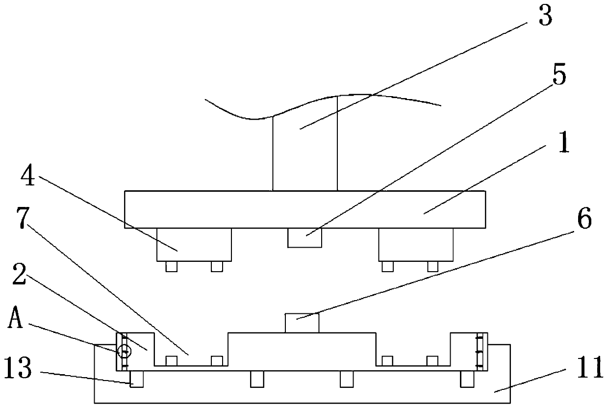
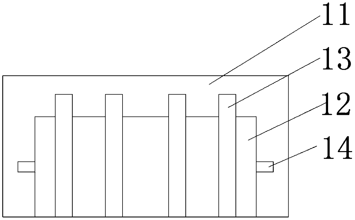
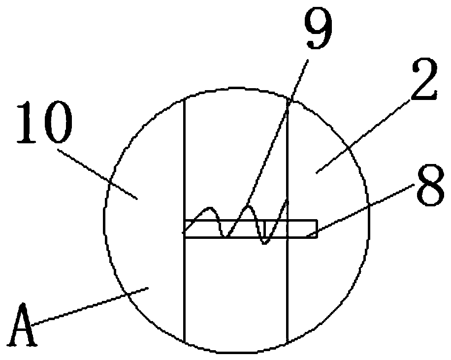
[0022] see Figure 1-4 , the present invention provides a terminal continuous stamping die, including an upper die 1 and a lower die 2, the top of the upper die 1 is fixedly connected to the bottom of the output shaft 3 of the hydraulic press, and the bottom of the upper die 1 is fixedly connected with punching heads in sequence from left to right 4 and the positioning sleeve 5, the top of the lower mold 2 is fixedly connected with a positioning rod 6, the pos...


PUM


Abstract

The invention belongs to the technical field of dies, in particular to a continuous stamping die for terminals. The continuous stamping die comprises an upper die and a lower die, wherein the top of the upper die is fixedly connected with the bottom of a hydraulic machine output shaft; the bottom of the upper die is sequentially and fixedly connected with stamping die heads and a positioning sleeve from left to right; the top of the lower die is fixedly connected with a positioning rod; a concave die head is arranged on the top of the lower die; through holes formed in the two side faces of the lower die are internally connected with telescopic rods in a clamping manner; the surfaces of the telescopic rods are connected with springs in a sleeving manner; one end of each of the springs is fixedly connected with the side face of the lower die while the other end of each of the springs is fixedly connected with a clamping plate; and the bottom of the lower die is in lap joint with a die seat. The continuous stamping die for the terminals disclosed by the invention has the advantages that through arrangement of the die seat, positioning grooves, a lower die groove and clamping plates,the effect of positioning the lower die is achieved; through arrangement of die releasing holes, the effect that the die releasing holes are in butt joint with a mechanical hand is achieved; and through arrangement of lap joint of the lower die and the die seat, the effect of separating the lower die from the die seat is achieved.

Description

technical field [0001] The invention belongs to the technical field of molds, and in particular relates to a terminal continuous stamping mold. Background technique [0002] Terminal block is an accessory product used to realize electrical connection, which is industrially divided into the category of connectors. With the increasing degree of industrial automation and stricter and more precise industrial control requirements, the amount of terminal blocks is gradually increasing. With the development of the electronics industry, the use of terminal blocks is increasing, and there are more and more types. In addition to PCB board terminals, the most widely used ones are hardware terminals, nut terminals, spring terminals, etc. With the daily use of terminals, more and more are used, but terminals need to replace molds in the production process and carry out batching. Stamping greatly reduces production speed, increases labor costs, and brings unnecessary economic losses to ...

Claims


Application Information

Patent Timeline
Patent Type & Authority Applications(China)
IPC IPC(8): B21D37/08B21D37/12
CPCB21D37/08B21D37/12
Inventor 王猛顾东进陆文杰
Owner KUNSHAN YOURUIQUAN PRECISION COMPONENTS CO LTD
Why Eureka
Try Eureka