Electronic component full-automatic pin-shearing molding equipment based on vision robot

A technology of electronic components and forming equipment, which is applied in the field of fully automatic cutting and forming equipment for electronic components based on vision robots, can solve the problems of high equipment cost, low production efficiency, and small quantity of a single item, and reduce equipment costs and production costs. Improved processing efficiency and high flexibility

Pending Publication Date: 2019-07-02
中山雅特生科技有限公司
View PDF0 Cites 4 Cited by
  • Summary
  • Abstract
  • Description
  • Claims
  • Application Information

AI Technical Summary

Problems solved by technology

[0004] At present, the factory involves electronic components such as capacitors and rectifiers in various shapes and sizes, and there are many types, and the quantity of a single model is small. The existing automatic forming equipment on the market is basically a single material, a single material, and a single molding, which is impossible. For general purpose, such as feeding, the whole pile of bulk electronic components is first sent to the rectifier channel by using a vibrating plate, and then screened by the screening structure designed in the rectifier channel, and finally the final positioning is completed by the claws at the end of the rectifier channel. The method is suitable for compone

Method used


Image

  • Electronic component full-automatic pin-shearing molding equipment based on vision robot
  • Electronic component full-automatic pin-shearing molding equipment based on vision robot
  • Electronic component full-automatic pin-shearing molding equipment based on vision robot

Examples


Example Embodiment

[0040] The present invention will be further described below in conjunction with the drawings:

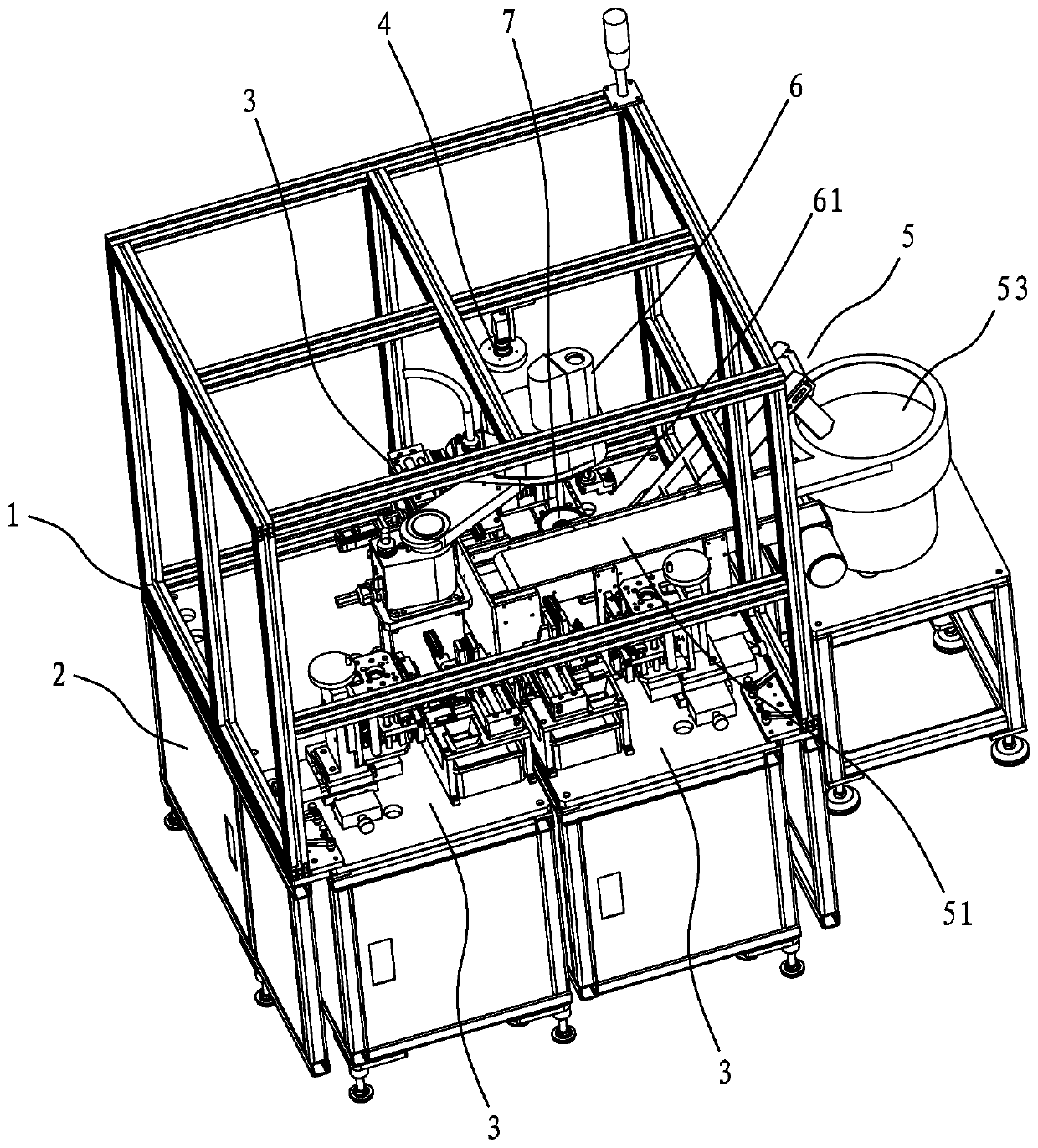
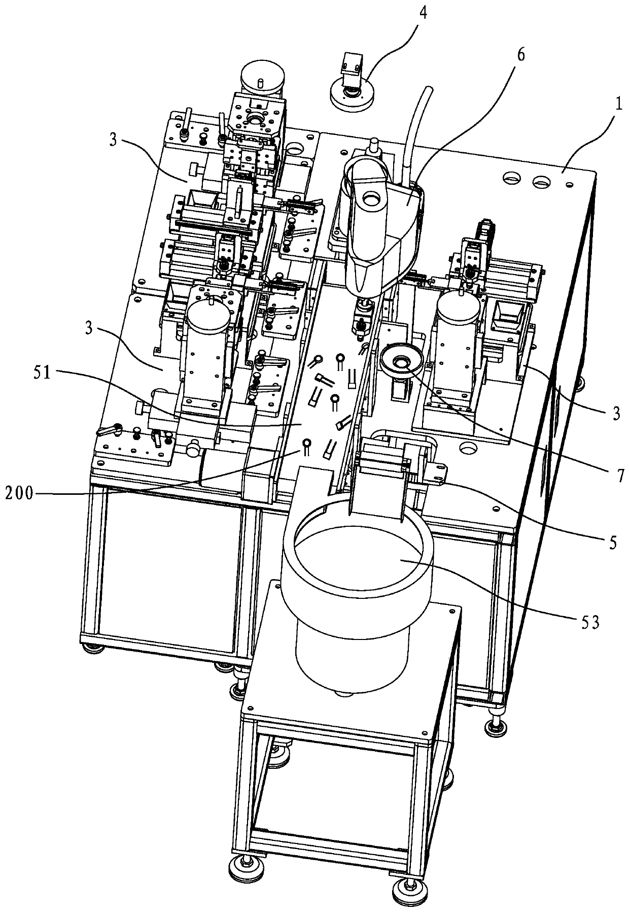
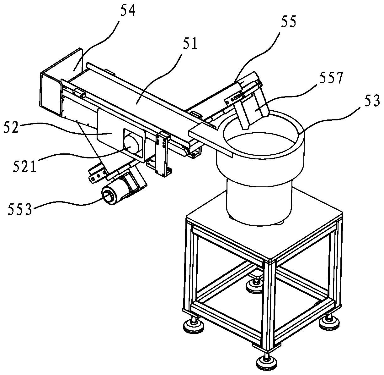
[0041] Such as Figure 1 to Figure 11 The automatic foot-cutting and shaping equipment for electronic components based on vision robots is shown, including a machine 1 and an industrial computer 2. The machine 1 is provided with a plurality of different designated electronic components for cutting feet and The cutting foot forming mechanism 3 is formed. The machine 1 is provided with a four-axis manipulator 6, the manipulator 6 is provided with a first vacuum suction nozzle 61 for sucking electronic components, and the machine 1 is provided with a The electronic components 200 in a variety of random states are circulatedly supplied to the feeding mechanism 5 within the suction range of the first vacuum suction nozzle 61. The upper end of the machine 1 is provided with a downward photograph to detect the position of the electronic components on the feeding mechanism 5 And the type and...


PUM


Abstract

The invention discloses electronic component full-automatic pin-shearing molding equipment based on a vision robot. The electronic component full-automatic pin-shearing molding equipment includes a machine table, an industrial personal computer, a four-axis manipulator, a feeding mechanism and a plurality of pin-shearing molding mechanisms for pin-shearing and molding a variety of different electronic components, a first vacuum suction nozzle is formed in the manipulator, a first camera for photographing downwards and a second camera for photographing upwards are arranged at the upper end of the machine table, the first camera photographs and detects the electronic components in the suction range of the first vacuum suction nozzle, the location and type of the designated electronic components are determined and fed back to the industrial personal computer, then the manipulator is controlled to move with the first vacuum suction nozzle to the location of the designated electronic components to suck and move to the position over the second camera to detect, and the manipulator adjusts the electronic components to the set angle and the set location according to feedback angle and location information of the electronic components from the second camera, and moves to the processing position of the pin-shearing molding mechanisms corresponding to the electronic components for pin-shearing and molding.

Description

[0001] 【Technical field】 [0002] The invention relates to a fully automatic cutting foot forming equipment based on vision robot electronic components. [0003] 【Background technique】 [0004] At present, the factory involves electronic components such as capacitors and rectifiers in various shapes and sizes, and there are many types, and the quantity of a single model is small. The existing automatic forming equipment on the market is basically a single material, a single material, and a single molding, which is impossible. For general purpose, such as feeding, the whole pile of bulk electronic components is first sent to the rectifier channel by using a vibrating plate, and then screened by the screening structure designed in the rectifier channel, and finally the final positioning is completed by the claws at the end of the rectifier channel. The method is suitable for components with a single shape and has the characteristics of high efficiency and stable operation. Howeve...

Claims


Application Information

Patent Timeline
IPC IPC(8): B21F11/00B21F1/00B21F23/00
CPCB21F11/00B21F1/004B21F23/00
Inventor 温友密杨云姚佳
Owner 中山雅特生科技有限公司
Why Eureka
Try Eureka