
Welding auxiliary device

An auxiliary device and accommodating slot technology, applied in auxiliary devices, welding/cutting auxiliary equipment, welding equipment, etc., can solve the problems of reducing welding quality, increasing wire frame error, time-consuming and laborious welding, etc., and reducing welding quality. , the effect of preventing displacement

Pending Publication Date: 2019-07-02
东莞市东晓五金制品有限公司
View PDF0 Cites 0 Cited by
  • Summary
  • Abstract
  • Description
  • Claims
  • Application Information

AI Technical Summary

Problems solved by technology

[0002] In the production process of the product, many products will be manufactured using welding process. The general container-type grille is composed of multiple vertical and horizontal intersecting wire frame strips. Before welding, the multiple vertical and horizontal intersecting wire frame strips need to use jigs Fix the side that needs to be welded. When welding, the worker welds each node of the wire frame strip on this side, and the jig needs to be removed after each side is welded, and then installed on the lower side of the container type grille Welding is time-consuming and labor-intensive, and requires multiple loading and unloading fixtures, which can easily increase the error between the wire frame strips and reduce the quality of welding

Method used


Image

  • Welding auxiliary device
  • Welding auxiliary device
  • Welding auxiliary device

Examples


Embodiment Construction

[0015] In order to make the technical problems, technical solutions and beneficial effects to be solved by the present invention clearer, the present invention will be further described in detail below in conjunction with the accompanying drawings and embodiments. It should be understood that the specific embodiments described here are only used to explain the present invention, not to limit the present invention.

[0016] It should be noted that when a component is referred to as being “fixed on” or “disposed on” another component, it may be directly on the other component or indirectly on the other component. When an element is referred to as being "connected to" another element, it can be directly or indirectly connected to the other element.

[0017] It is to be understood that the terms "length", "width", "top", "bottom", "front", "rear", "left", "right", "vertical", "horizontal", "top" , "bottom", "inner", "outer" and other indicated orientations or positional relations...


PUM


Abstract

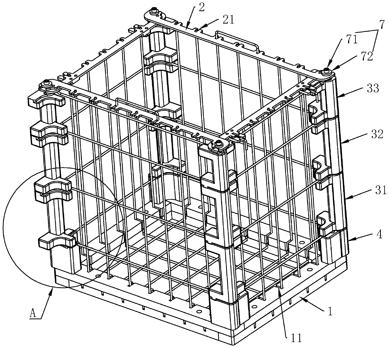
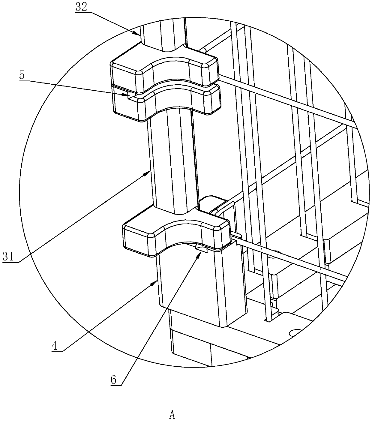
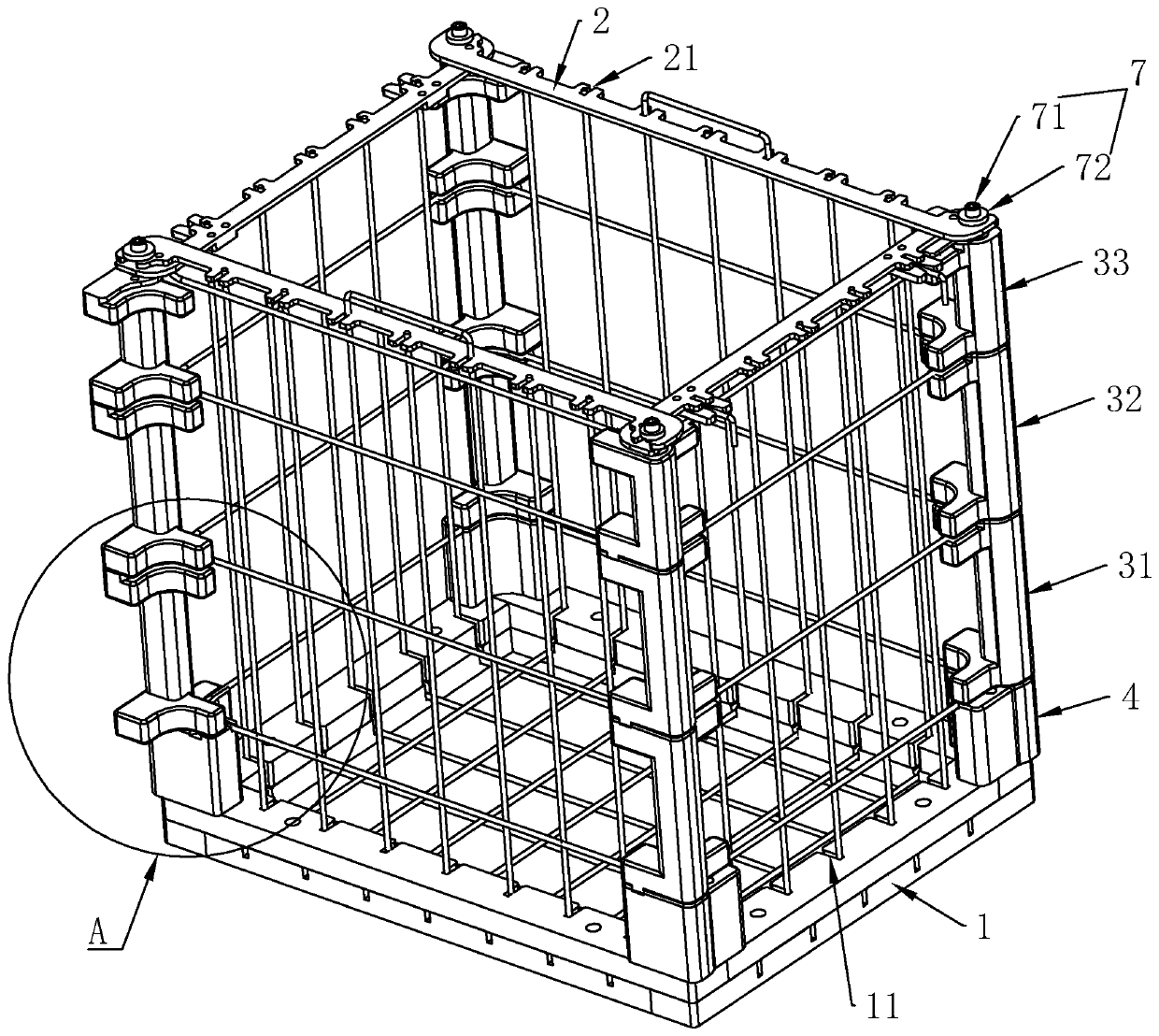
The invention relates to the technical field of machining auxiliary equipment, in particular to a welding auxiliary device. The welding auxiliary device comprises a bottom frame in a rectangle shape,wherein fixing rods are fixedly connected to the four corners of the bottom frame, and the fixing rods are arranged perpendicular to the bottom frame; a plurality of pairs of first positioning groovesdistributed in a spaced mode are correspondingly formed in opposite seamed edges of the bottom frame, and each pair of the first positioning grooves is used for containing a [-shaped bending angle ofa linear frame strip; positioning clamping plates are detachably connected to the ends, away from the bottom frame, of adjacent fixing rods, and second positioning grooves corresponding to first positioning grooves in the bottom frame are formed in the positioning clamping plates in the length direction of the positioning clamping plates; and the welding auxiliary device further comprises rotating handles, fixing blocks are fixedly connected to the ends, near the bottom frame, of the fixing rods, containing grooves are correspondingly formed in the rotating handles and the fixing blocks, andthe containing grooves are used for containing bending angles of linear frame rings. The welding auxiliary device improves the efficiency and quality of welding, and is time-saving and labor-saving.

Description

technical field [0001] The invention relates to the technical field of product processing auxiliary equipment, in particular to a welding auxiliary device. Background technique [0002] In the production process of the product, many products will be manufactured using welding process. The general container-type grille is composed of multiple vertical and horizontal intersecting wire frame strips. Before welding, the multiple vertical and horizontal intersecting wire frame strips need to use jigs Fix the side that needs to be welded. When welding, the worker welds each node of the wire frame strip on this side, and the jig needs to be removed after each side is welded, and then installed on the lower side of the container type grille Welding is time-consuming and labor-intensive, and requires multiple loading and unloading of jigs, which easily increases the error between wire frame strips and reduces the quality of welding. Contents of the invention [0003] In view of th...

Claims


Application Information

Patent Timeline
IPC IPC(8): B23K11/36B23K37/04B23K101/22
CPCB23K11/36B23K37/0443
Inventor 谭勤锋杜四清
Owner 东莞市东晓五金制品有限公司
Learn More