Method for sucking liquid in vacuum negative pressure state

A technology of vacuum suction and negative pressure, which is applied in the direction of liquid variable displacement machinery, pump control, non-variable displacement pumps, etc. It can solve the problems of unreachable suction equipment, impurities, high cost, etc., and achieve reduction in equipment volume and operation Integrity, wide selection range, and the effect of improving the service life

Inactive Publication Date: 2019-07-02
黄海峰
View PDF5 Cites 0 Cited by
  • Summary
  • Abstract
  • Description
  • Claims
  • Application Information

AI Technical Summary

Problems solved by technology

The inventor used hundreds of pumps of various styles in the process of equipment research and development and manufacturing. The pumps with good self-priming ability all have the characteristics of high cost, short maintenance period, unstable performance, and limited scope of application. In the field, it may involve various complex working conditions such as high temperature, acid and alkali, solvent, explosion-proof, impurities in the medium, vacuum pressure may be lower than -0.05Mpa low vacuum, and may be higher than -0.08Mpa high vacuum , under these working conditions, the existing various suction equipment have not achieved the ideal performance for industrial applications, and no method with low cost, simple operation, stable performance and wide adaptability has been found from various literature records. , but the modern industry pursues the continuity of the process, and it is of great significance to properly solve the suction problem of the liquid in the vacuum negative pressure state under various working conditions

Method used


Image

  • Method for sucking liquid in vacuum negative pressure state
  • Method for sucking liquid in vacuum negative pressure state
  • Method for sucking liquid in vacuum negative pressure state

Examples


Embodiment example 1

[0025] A method for pumping liquid under vacuum negative pressure.

[0026] The vacuum tank type oil-water separation device of the oil filter adopts a continuous working system, and uses low-temperature vacuum evaporation to remove moisture in the oil. The vacuum in the vacuum tank is generated by a vacuum exhaust device, and the oil after removing moisture is in a vacuum Under negative pressure, it needs to be continuously output from the vacuum tank, and the separated oil may not be sucked out by using a common high-suction pump, but it can be reliably realized according to the method of the present invention, and the measures are as follows:

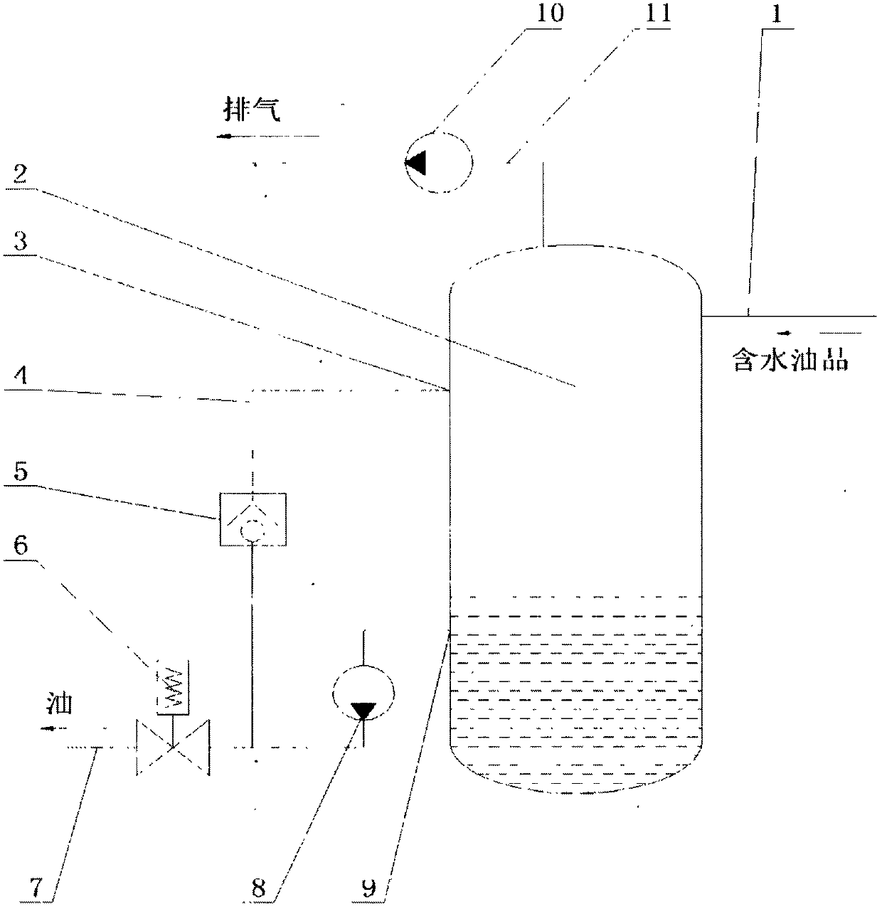
[0027] The water-containing oil enters the vacuum separation tank 2 from the liquid inlet pipeline 1, and the vacuum in the tank is maintained by the vacuum pump 10 and the exhaust pipeline 11; a liquid outlet 9 is opened at a height below the oil level in the vacuum separation tank 2, and is installed in the vacuum separation tank 2....

Embodiment example 2

[0029] A method for pumping liquid under vacuum negative pressure.

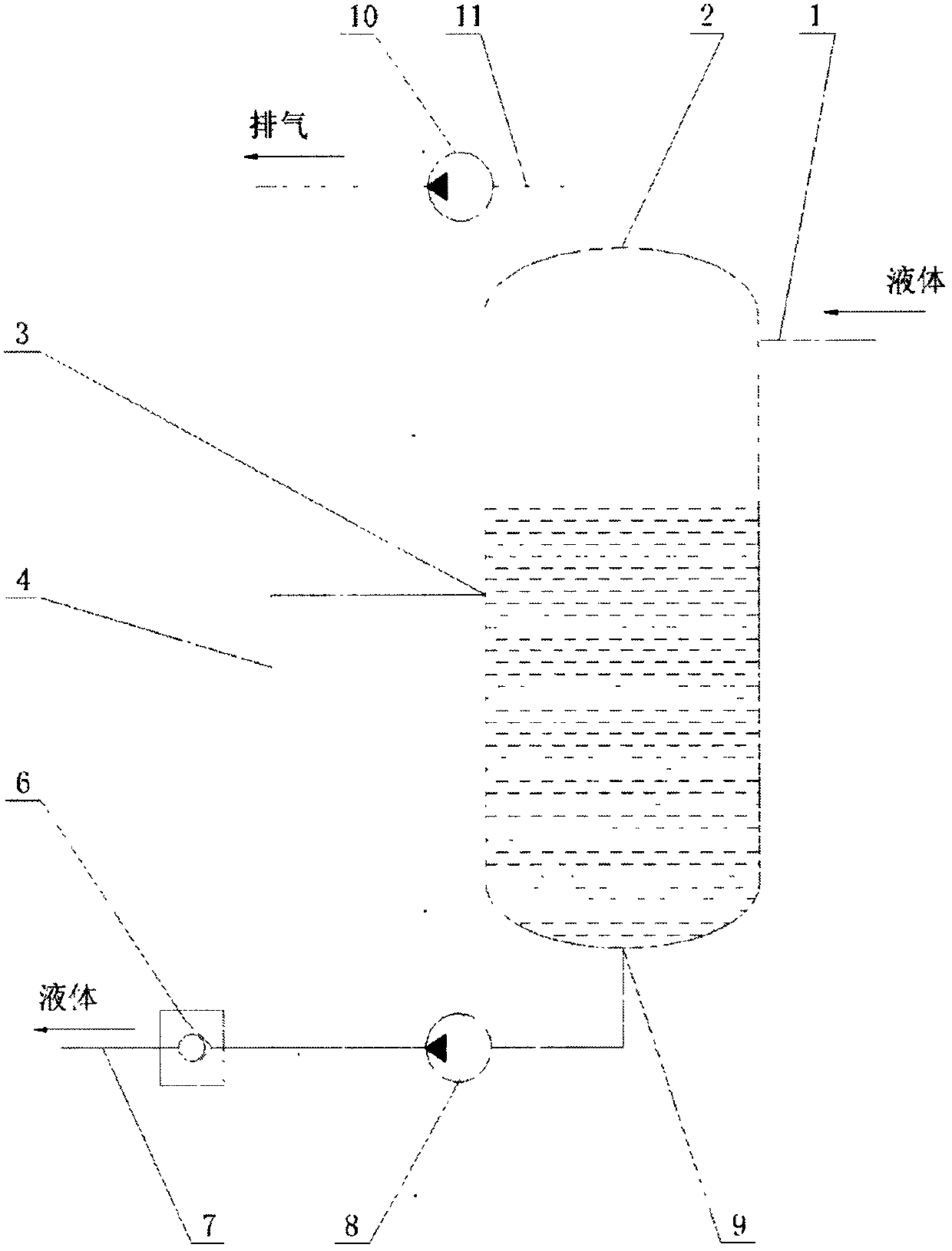
[0030] The vacuum degassing device used to remove gas in water, the liquid enters the vacuum separation tank 2 from the liquid inlet pipeline 1 under negative pressure (in this case, the vacuum degassing tank), the height below the liquid surface in the vacuum separation tank 2 Open a liquid outlet 9, communicate with the inlet of the suction device 8 (in this case, a centrifugal pump) installed below this height, communicate with the valve 6 and the output pipeline 7 at the outlet of the suction device 8, where the valve 6 It is a one-way valve; a pipeline is set up between the outlet of the suction device and the one-way valve to communicate with the vacuum separation tank 2 through a damping tube as a pressure balance pipeline 4; the pressure balance pipeline 4 is opened on the vacuum separation tank 2 The pressure balance port 3 is higher than the liquid outlet 9; in this case, the vacuum pump 11 is used ...


PUM


Abstract

A method for sucking liquid in a vacuum negative pressure state is characterized in that an opening is formed below the liquid level of a negative pressure sealed container, and the opening communicates with an inlet of a suction device in a sealed mode; an outlet of the suction device communicates with a valve and an output pipeline, and a damping balance pipeline is arranged between the outlet of the pump and the valve and communicates with the space above the liquid level in the sealed container.

Description

[0001] Field [0002] The invention belongs to the field of fluid technology, and in particular relates to the technology of using common fluid conveying devices (such as pumps) to pump liquid under vacuum and negative pressure Background technique [0003] The process of treating fluids in a vacuum state has been used more and more, some are to separate the gas in the liquid with a vacuum state; some are to reduce the contact between the liquid and the external gas; Stirring and extrusion of the pump cause emulsification, and various industrial applications such as vacuum conveying and separation in a vacuum state, especially in the separation of oil and water, the separation method in a vacuum state has achieved good results. [0004] In these industrial applications, the liquid in the vacuum container needs to be transported out in the end. If it is a process of intermittent operation, the vacuum can be released, and then the liquid can be pumped to the designated place by ...

Claims


Application Information

Patent Timeline
Patent Type & Authority Applications(China)
IPC IPC(8): F04B49/22F04B49/24F04B23/04F04B37/14F04C14/24F04C14/26F04D15/00
CPCF04B23/04F04B37/14F04B49/22F04B49/24F04C14/24F04C14/26F04D15/0005
Inventor 黄海峰
Owner 黄海峰
Why Eureka
Try Eureka