Heavy pre-pressing high-rigidity narrow linear guide rail device

A linear guide, high rigidity technology, applied in the direction of linear motion bearings, bearings, shafts and bearings, etc., can solve the problems of increased frictional resistance of linear guides, affecting the accuracy of product processing, insufficient rigidity of linear guides, etc., to reduce the driving force. The effect of energy, smooth operation, increased flexibility and machining accuracy

Pending Publication Date: 2019-07-02
SUZHOU HUAZHENG IND TECH CO LTD
View PDF6 Cites 0 Cited by
  • Summary
  • Abstract
  • Description
  • Claims
  • Application Information

AI Technical Summary

Problems solved by technology

[0005] The purpose of the present invention is to overcome the problem that the contact area between the rollers of the linear guide rail and the guide rail is small when the existing linear guide rail is loaded with a high weight. Lateral tension, the rollers in the slider are prone to offset, and at the same time fluctuate due to the influence of rolling resistance, the friction resistance of the linear guide increases, resulting in easy deformation of the linear guide and reduced rigidity. Due to the lack of rigidity of the linear guide, in precision machinery Vibration occurs during processing, which affects the accuracy of product processing and even leads to product scrapping. However, the width of the linear guide rail slider is relatively large. In high-precision product processing, the guidance and operation flexibility of the slider can no longer meet the requirements of high-precision products. To meet the technical problem of product processing requirements, a heavy preloaded high rigidity narrow linear guide device is provided to solve the above problems

Method used


Image

  • Heavy pre-pressing high-rigidity narrow linear guide rail device
  • Heavy pre-pressing high-rigidity narrow linear guide rail device
  • Heavy pre-pressing high-rigidity narrow linear guide rail device

Examples


Embodiment Construction

[0020] In view of the deficiencies in the prior art, the case has been studied for a long time and a large amount of practice, and the technical scheme of the present invention can be proposed. The technical solutions in the embodiments of the present invention will be clearly and completely described below in conjunction with the accompanying drawings in the embodiments of the present invention.

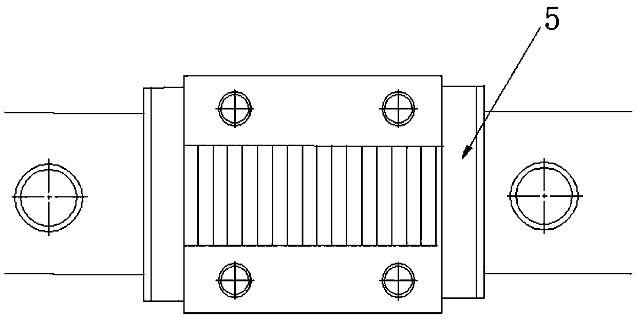
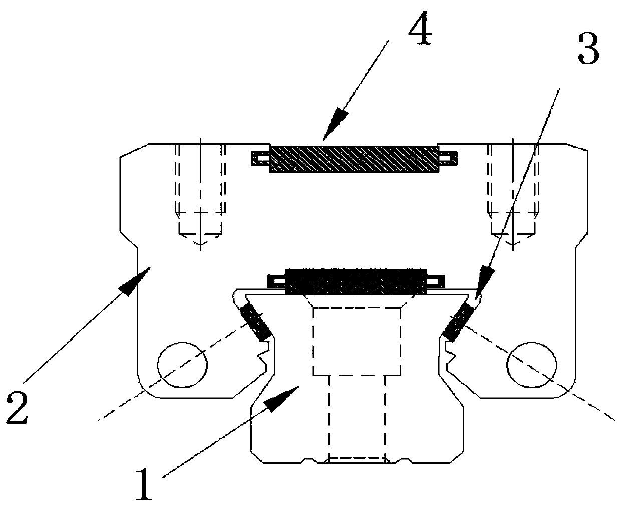
[0021] figure 1 It is a cross-sectional view of a heavy preloaded high rigidity narrow linear guideway device; figure 2 It is a schematic diagram of the structure of a heavy preloaded high rigidity narrow linear guideway device. Such as figure 1 and figure 2 As shown, a heavy preloaded high-rigidity narrow linear guide rail device provided in the embodiment of the present invention includes: a guide rail 1 and a slider 2 matched with it, and there are a row of small rollers on the left and right sides of the slider 2 3. There is a row of large rollers 4 located around slider 2...


PUM


Abstract

The invention discloses a heavy pre-pressing high-rigidity narrow linear guide rail device. A guide rail (1) and a sliding block (2) matched with the guide rail (1) are included. Each of the left sideand the right side of the sliding block (2) is provided with a row of small pin rollers (3), a row of big pin rollers (4) are located between small pin rollers (3) on the left side and the right sideof the sliding block (2), the high-rigidity design that length is 4-6 times of the diameter is adopted in the big pin rollers (4), the width size of the sliding block (2) is 34-248 mm, and returners(5) are arranged at the two ends of the sliding block (2). According to the heavy pre-pressing high-rigidity narrow linear guide rail device, through high-rigidity design of the big pin rollers, pre-pressing of a linear guide rail is increased, the contact gap between the pin rollers and the guide rail is reduced, accordingly, the contact area between the pin rollers and the guide rail is increased, precision of the linear guide rail is gradually improved, and accordingly the service life of the linear guide rail is greatly prolonged. Through the narrow design of the width size of the slidingblock, guiding and running flexibility of the sliding block is greatly improved, the size of a precision machine table is reduced, and flexibility and machining precision of the machine table are improved.

Description

technical field [0001] The invention relates to the technical field of linear guide devices, in particular to a linear guide rail device, in particular to a heavy preloaded high-rigidity narrow-width linear guide rail device. Background technique [0002] Linear guide rails, also known as line rails, slide rails, linear guide rails, and linear slide rails, are used in linear reciprocating motion applications, and can bear a certain torque, and can achieve high-precision linear motion under high load conditions. Linear guideway is a kind of rolling guide device, which is composed of rollers rolling infinitely between the slider and the guide rail, so that the load platform can easily move along the guide rail with high precision linear motion, and the friction coefficient is reduced to the usual traditional sliding guide One-fiftieth of that, it can easily achieve high positioning accuracy. [0003] Linear guide rails are more and more widely used in the machine industry. Li...

Claims


Application Information

Patent Timeline
Patent Type & Authority Applications(China)
IPC IPC(8): F16C29/02
CPCF16C29/02
Inventor 单宪民王善良
Owner SUZHOU HUAZHENG IND TECH CO LTD
Why Eureka
Try Eureka