Fast-response redundant membrane type thermocouple

A thermocouple, fast-response technology, applied in thermometers using electrical/magnetic components directly sensitive to heat, measuring heat, using electrical devices, etc., can solve problems such as shortening the service life of heated components, large failures, and economic losses Achieve the effect of avoiding inaccurate measurement results, improving accuracy, and widening temperature measurement range

Pending Publication Date: 2019-07-02
HARBIN UNIV OF SCI & TECH
View PDF0 Cites 0 Cited by
  • Summary
  • Abstract
  • Description
  • Claims
  • Application Information

AI Technical Summary

Problems solved by technology

The second is to choose a sensor with a small time constant. However, there is no suitable fast-response temperature sensor available in the domestic temperature product market. If the internal temperature of the gas turbine exceeds the tolerance range of the heating part of the gas turbine hot channel, it will lead to a serious shortening of the heating part. service life, more serious will lead to large-scale failure, resulting in certain economic losses and even casualties

Method used


Image

  • Fast-response redundant membrane type thermocouple
  • Fast-response redundant membrane type thermocouple
  • Fast-response redundant membrane type thermocouple

Examples


Embodiment 1

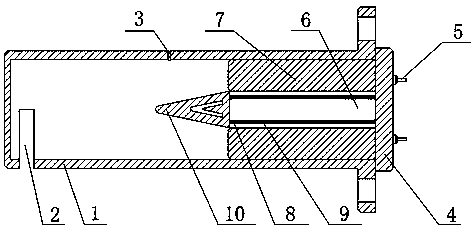
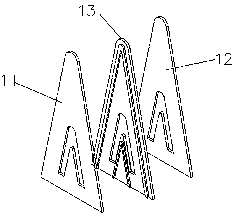
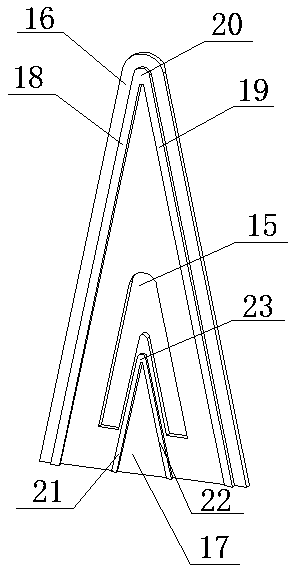
[0020] see Figure 1-3 , the present invention provides a technical solution: a fast-response redundant membrane thermocouple, including a stagnation cover 1, an air inlet 2 is provided on one side of the stagnation cover 1, and an upper end of the stagnation cover 1 is provided with The air outlet 3, the terminal block 4 is installed on one side of the stagnation cover 1, the terminal block 4 is provided with a wiring port 5, the inner cavity of the stagnation cover 1 is also provided with a fixed seat 6, and the fixed seat 6 One end of the terminal block 4 is connected to one side, and high-temperature cement 7 is filled between both sides of the fixed seat 6 and the inner side of the stagnation cover 1, and a lead wire protection tube 8 is provided inside the fixed seat 6, and the lead wire protection tube 8 is penetrated inside. There is a lead wire 9, the other end of the fixing seat 6 is connected to a sandwich structure 10, and the sandwich structure 10 is connected to ...

Embodiment 2

[0023] Such as Figure 4 As shown, one side of the stagnation cover 1 is provided with an air inlet 2, the upper end of the stagnation cover 1 is provided with an air outlet 3, one side of the stagnation cover 1 is installed with a terminal block 4, and the terminal block 4 is provided with Wiring port 5, the inner cavity of the stagnation cover 1 is also provided with a fixing seat 6, and one end of the fixing seat 6 is connected to one side of the wiring seat 4, and a high temperature is filled between both sides of the fixing seat 6 and the inner side of the stagnation cover 1 Cement 7, the inside of the fixed base 6 is provided with a lead wire protection tube 8, and the inside of the lead wire protection tube 8 is threaded with a lead wire 9, and also includes a corundum tube 24, the corundum tube 24 is arranged between the high temperature cement 7, and the One end of the corundum tube 24 is connected to the fixed seat 6, and a dual wire protection tube 25 is installed i...


PUM


Abstract

The invention discloses a fast-response redundant membrane type thermocouple, comprising a stagnation cover. An air inlet is formed in one side of the stagnation cover; an air outlet is formed in theupper end of the stagnation cover; and a connecting seat is installed at one side of stagnation cover. A connecting port is formed in the connecting seat. A fixed base is arranged in the inner cavityof the stagnation cover; and one end of the fixed seat is connected with one side of the connecting seat. The space between the two sides of the fixed seat and the inner side of the stagnation cover is filled with high temperature cement. A lead protection tube is arranged inside the fixed seat; and a lead penetrates the inside of the lead protection tube. A sandwich structure is connected to theother end of the fixed seat and is connected with a lead. On the basis of the novel structure, the thermocouple has advantages of fast sensor response, large temperature measurement range, and high measurement precision. The necessary testing way is provided for domestication of the existing new-generation high-power combustion gas turbine; and the demand of development of the combustion gas turbine technology is satisfied.

Description

technical field [0001] The invention relates to the technical field of thermocouples, in particular to a fast-response redundant membrane thermocouple. Background technique [0002] As a new type of ship power equipment, the gas turbine is known as the crown jewel of the industry. It is the embodiment of a country's comprehensive strength and is of great significance to enhance the ocean transportation capacity, improve the energy structure and realize the sustainable development of the environment. The exhaust temperature of the gas turbine affects the combustion. The output power and thermal efficiency of the gas turbine, the temperature control is ultimately to control the gas turbine inlet temperature. Using the relationship between the gas turbine inlet temperature and the gas turbine exhaust temperature, measure the gas turbine exhaust temperature, and indirectly obtain the gas turbine inlet temperature, so as to control the gas turbine output power and thermal efficie...

Claims


Application Information

Patent Timeline
Patent Type & Authority Applications(China)
IPC IPC(8): G01K7/10G01K7/14
CPCG01K7/10G01K7/14
Inventor 于广滨陈杰
Owner HARBIN UNIV OF SCI & TECH
Why Eureka
Try Eureka