Tidal-flat area aquaculture pond automatic aerator

An aquaculture, automatic oxygenation technology, applied in fish farming, application, animal husbandry and other directions, can solve the problems of untimely, inaccurate, inconvenient, etc., achieve deep oxygenation depth, energy saving, good oxygenation effect Effect

Pending Publication Date: 2019-07-05
YANCHENG TEACHERS UNIV
View PDF0 Cites 4 Cited by
  • Summary
  • Abstract
  • Description
  • Claims
  • Application Information

AI Technical Summary

Problems solved by technology

[0002] The aerator is an essential device for aquaculture. The existing aerators mainly have two forms: one is a semi-submersible aerator that floats on the water surface and sprays around, and is used for timing aeration in field aquaculture ponds. , the other is to insert one end of the leather tube into the water, and the other end of the leather tube is connected to the aerator of the oxygen pump, which is used for continuous oxygenation of indoor fish tanks. In recent years, there are also some aerators that use solar energy as energy. And it can be controlled remotely. However, due to the fact that in the field aquaculture pools, especially tidal aquaculture pools, the water temperature, salinity, pH and oxygen content of the pool water in different regions, different seasons, and different periods are not the same. The amount will change with the change of breeding time, breeding density, breeding method and weather. The change of oxygen content in the breeding pond is directly related to the effect of aquaculture. In the past, it was based on the breeding experience and manual opening of the aerator. Control the oxygenation of the pool water, and the tidal flat is located in a remote place, far away from the urban area. It is not convenient, timely and accurate to use the method of manually controlling the oxygenation machine.

Method used


Image

  • Tidal-flat area aquaculture pond automatic aerator
  • Tidal-flat area aquaculture pond automatic aerator
  • Tidal-flat area aquaculture pond automatic aerator

Examples


Embodiment Construction

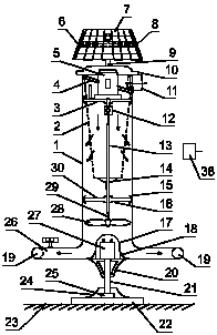
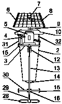
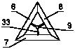
[0020] 1. According to Figure 1 to Figure 6 , consisting of a barrel body (1), a filter screen (2), a second horizontal support (3), an oblique support (4), a motor (5), a first photovoltaic panel (6), a second photovoltaic panel (7), The third photovoltaic panel (8), vertical support (9), bucket cover (10), air inlet (11), universal joint (12), bushing (13), bottom support (14), arc edge (15 ), six-way (16), fairing (17), sealing ring (18), air outlet (19), barrel support (20), bottom shaft (21), base (22), cement seat (23), bearing Cover (24), bearing (25), air outlet pipe (26), battery (27), fan blade (28), main shaft (29), third transverse support (30), inner barrel (31), inner port (32) , the first transverse support (33), air pressure sensor (34), water body sensor group (35), control circuit board (36), sonar transmitter (37) and sonar receiver (38).

[0021]2. Cement seat (23), base (22) and bearing cap (24) constitute fixed part, staving (1), fairing cover (17), ai...


PUM


Abstract

The invention provides a tidal-flat area aquaculture pond automatic aerator. A cement seat, a base and a bearing cover form a fixing part, a barrel, a fairing, an air inlet, an air outlet pipe, an airoutlet, a bucket support and a bottom shaft form an active part, a filter net, a lateral bracket, a diagonal bracket, a bucket lid and a casing form a follow-up assembly, a photovoltaic panel and a vertical frame form a new energy assembly, a motor, a spindle and blades form a power assembly, a sonar transmitter and a sonar receiver form an information sending and receiving part, the aerator canautomatically detect the water quality index of a breeding pond, the monitoring data is more comprehensive, the aerator can automatically control the start and stop of the aerator according to the meteorological pressure parameter and the dissolved oxygen parameter of the water, automatic aeration is achieved, aeration is achieved in time, and the aerator does not require manual intervention, usessolar energy as electric energy, saves energy, has deeper oxygenation depth, has a better oxygenation effect, can conduct monitoring in the vicinity of the breeding pond by wireless transmission andcan be applied to the aquaculture technology field and the development of tidal-flat area resources.

Description

technical field [0001] The invention relates to an aerator for aquaculture ponds, in particular to an automatic aerator for tidal flat aquaculture ponds, belonging to the technical field of aquaculture. Background technique [0002] The aerator is an essential device for aquaculture. The existing aerators mainly have two forms: one is a semi-submersible aerator that floats on the water surface and sprays around, and is used for timing aeration in field aquaculture ponds. , the other is to insert one end of the leather tube into the water, and the other end of the leather tube is connected to the aerator of the oxygen pump, which is used for continuous oxygenation of indoor fish tanks. In recent years, there are also some aerators that use solar energy as energy. And it can be controlled remotely. However, due to the fact that in the field aquaculture pools, especially tidal aquaculture pools, the water temperature, salinity, pH and oxygen content of the pool water in differe...

Claims


Application Information

Patent Timeline
Patent Type & Authority Applications(China)
IPC IPC(8): A01K63/04
CPCA01K63/042
Inventor 冯越唐伯平张华彬张代臻宣富君汪正飞
Owner YANCHENG TEACHERS UNIV
Why Eureka
Try Eureka