Method for artificially synthesizing platelets in vitro in fluid movement mode

A fluid movement and artificial synthesis technology, applied in the field of machinery, can solve problems such as ineffective platelet transfusion and lack of platelet sources, and achieve a huge output effect

Inactive Publication Date: 2019-07-05
南京市江宁医院
View PDF5 Cites 5 Cited by
  • Summary
  • Abstract
  • Description
  • Claims
  • Application Information

AI Technical Summary

Problems solved by technology

[0003] The purpose of the present invention is to provide a method for artificially synthesizing platelets in vitro in a fluid movement mode, so as to solve the lack of source of platelets proposed in the above-mentioned background technology. Nowadays, platelets have been in a state of short supply in clinical practice and long-term regular transfusion of platelets is very easy to produce anti-inflammatory effects. Antibodies to platelets, causing problems with platelet transfusions not being effective

Method used


Image

  • Method for artificially synthesizing platelets in vitro in fluid movement mode
  • Method for artificially synthesizing platelets in vitro in fluid movement mode
  • Method for artificially synthesizing platelets in vitro in fluid movement mode

Examples


Embodiment 1

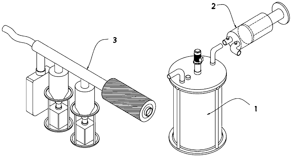
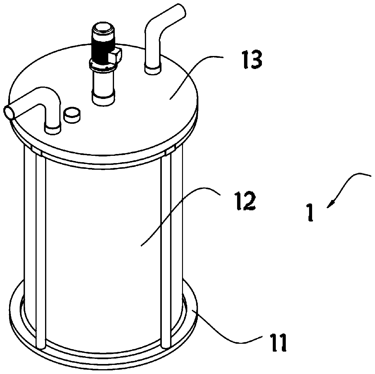
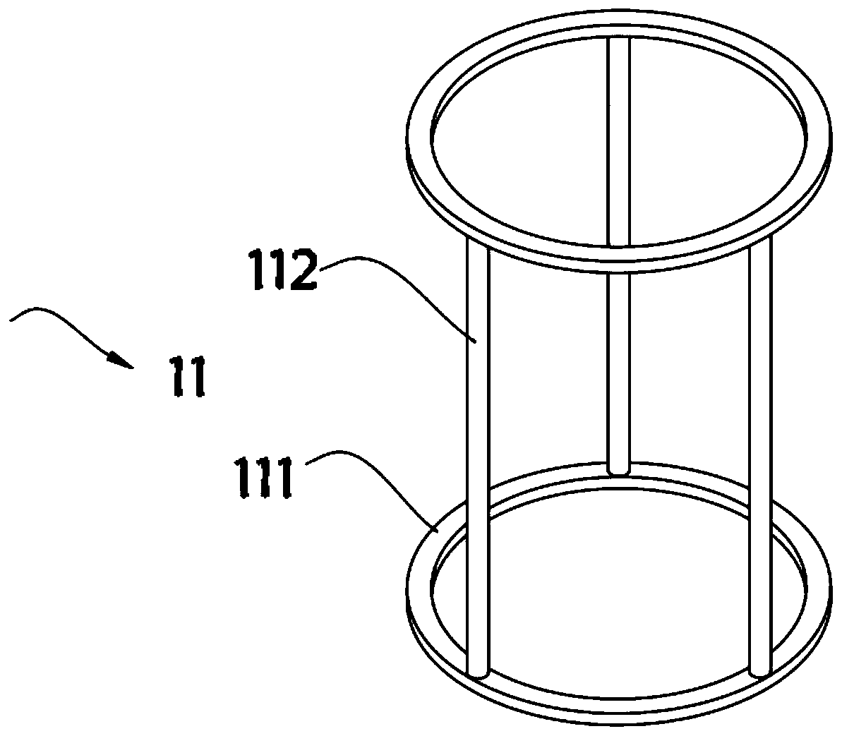
[0044] In one aspect, the present invention provides a device for artificially synthesizing platelets in vitro in a fluid movement mode, such as Figure 1 to Figure 7 As shown, it includes a platelet production device 1, a vacuum suction device 2, and a platelet enrichment device 3. The platelet production device 1 includes a placement frame 11 and a generation cylinder 12 arranged inside the placement frame 11. A snap ring 111, a plurality of connecting posts 112 are installed between the two snap rings 111, a top cover 13 is provided on the top of the generating cylinder 12, a turbulent flow system 14 is arranged inside the generating cylinder 12, and the turbulent flow system 14 includes a spline shaft 141, The bottom of the spline shaft 141 is equipped with an upper blade 142, the bottom of the upper blade 142 is equipped with a telescopic column 143, the bottom of the telescopic column 143 is equipped with a lower blade 144, and the top side of the top cover 13 is equipped...

Embodiment 2

[0052] As the second embodiment of the present invention, in the specific operation process, the turbulent flow system cannot be completely simulated only by the rotating blades. In order to obtain clean platelets, kinetic energy must be generated to force the quasi-platelets to split themselves. 141 to make improvements, as a preferred embodiment, such as Figure 8 to Figure 11 As shown, the upper end of the spline shaft 141 is equipped with an upper mounting plate 1411, the bottom of the upper mounting plate 1411 is provided with a fixed cylinder 1412, the inner top of the fixed cylinder 1412 is equipped with a telescopic cylinder 1413, and the bottom of the telescopic cylinder 1413 is provided with a connecting plate 1414 The top of the connecting plate 1414 is provided with a plurality of mounting screws 1415, the bottom of the connecting plate 1414 is provided with a telescopic shaft 1416, the top of the telescopic shaft 1416 is provided with a plurality of mounting holes ...

Embodiment 3

[0061] As a third embodiment of the present invention, in order to facilitate the vacuum adsorption of the culture solution, the inventors set up a vacuum suction device 2, as a preferred embodiment, such as Figure 12 As shown, the vacuum suction device 2 includes a hollow tube 21, a piston pad 22 is arranged inside the hollow tube 21, a push rod 23 is installed on one end of the piston pad 22, and a push plate 24 is arranged on the other end of the push rod 23. The outer wall of empty pipe 21 is equipped with liquid suction port 25 and liquid discharge port 26 respectively, and the outer wall of liquid suction port 25 and liquid discharge port 26 is all equipped with common valve 27, and liquid suction port 25 and liquid discharge port 26 are all connected with hollow tube. 21 connected.

[0062] In this embodiment, the piston pad 22 is made of rubber material, which has a certain degree of elasticity, and the overall sealing effect is good.

[0063] Further, the size of th...


PUM


Abstract

The invention relates to the technical field of machines, in particular to a method for artificially synthesizing platelets in vitro in a fluid movement mode. The method comprises a platelet generating device, a vacuum suction device and a platelet enriching device. According to a device and the method for artificially synthesizing platelets in vitro in a fluid movement mode, a turbulence device can be used to simulate a blood turbulence system in the body, induce platelet production, forcibly block quasi-platelet aggregation, and apply a kinetic energy that forces quasi-platelets to split thequasi-platelets self, so that clean platelets can be obtained, and platelet antibodies do not exist. The platelet yield produced by the method is huge, and there is no significant difference in the aspects of functions between mature platelets in the body and the produced platelets. The produced platelets can be directly applied to the clinic, and since the produced platelets is not screened by an in vivo immune system, the produced platelets are not obvious in antigenic property, and no platelet antibodies are generated.

Description

technical field [0001] The invention relates to the field of mechanical technology, in particular to a method for artificially synthesizing platelets in vitro in a fluid motion mode. Background technique [0002] At present, the platelets used clinically all come from the platelet donation in voluntary blood donation. Because donating platelets takes a long time, the wound is large, and the process of returning to the donor body through extracorporeal circulation makes the source of platelets scarce. Nowadays, platelets are clinically used. has been in short supply. Secondly, many patients with blood diseases need long-term regular platelet transfusions, which can easily produce anti-platelet antibodies, resulting in ineffective platelet transfusions and posing a major threat to the safety of patients' lives and property. Therefore, it is imperative to synthesize platelets in vitro. In recent years, some scientists have used the maturity of human induced pluripotent stem c...

Claims


Application Information

Patent Timeline
Patent Type & Authority Applications(China)
IPC IPC(8): B01J19/18B01J3/00B01J3/02B01J4/00B01J19/00
CPCB01J19/18B01J19/0066B01J19/0053B01J19/0006B01J4/001B01J3/006B01J3/02B01J2204/005C12M27/02
Inventor 印澄
Owner 南京市江宁医院
Why Eureka
Try Eureka