
Clamping device and inflating device

A clamping device and clamping component technology, applied in the field of mechanical equipment, can solve the problems of poor clamping firmness of the clamping device, difficulty in realizing automatic inflation, high working intensity, etc., achieve compact structure, ensure stability, and improve work efficiency Effect

Active Publication Date: 2019-07-05
青岛科力达机械制造有限公司
View PDF3 Cites 3 Cited by
  • Summary
  • Abstract
  • Description
  • Claims
  • Application Information

AI Technical Summary

Problems solved by technology

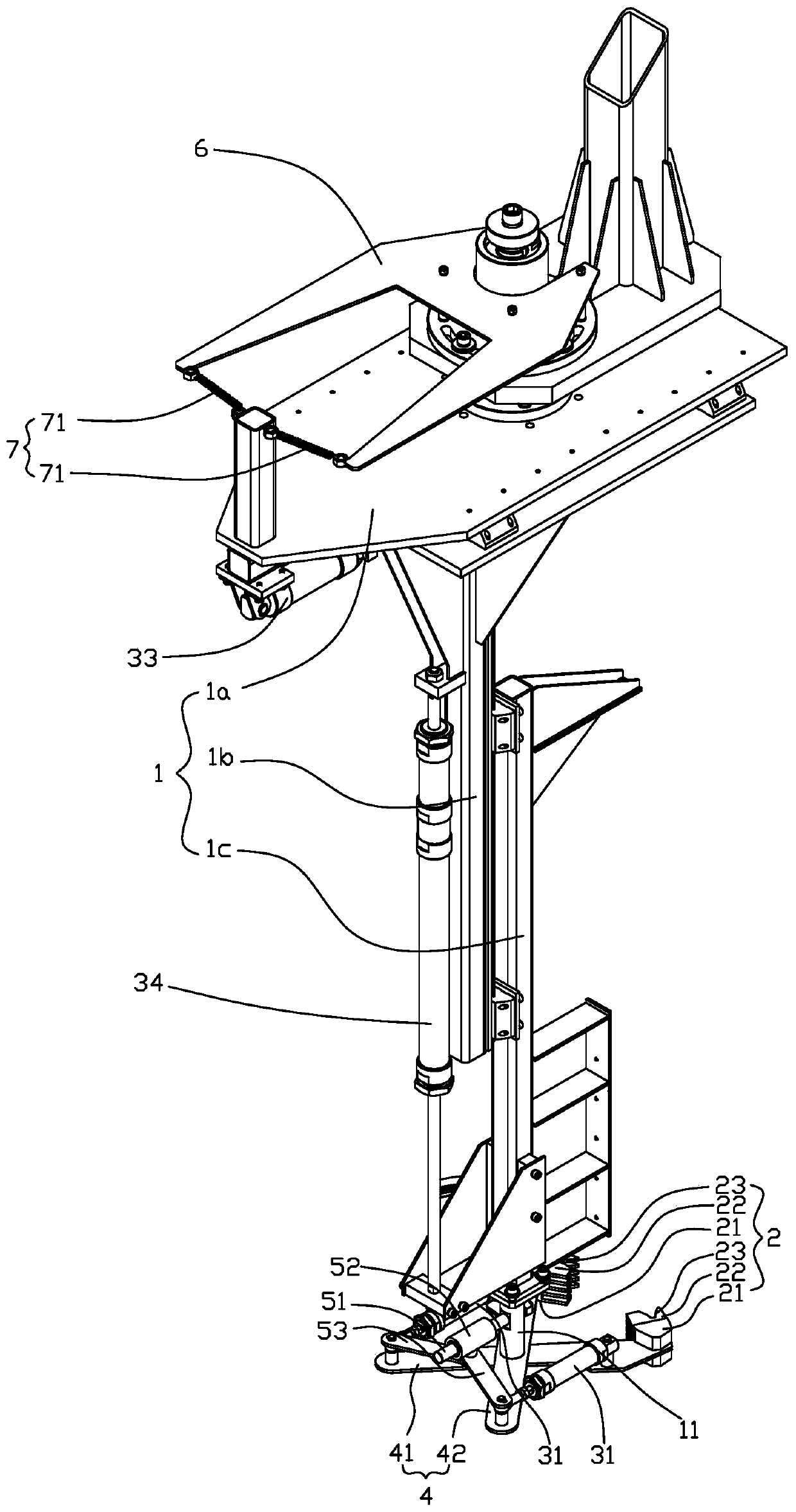
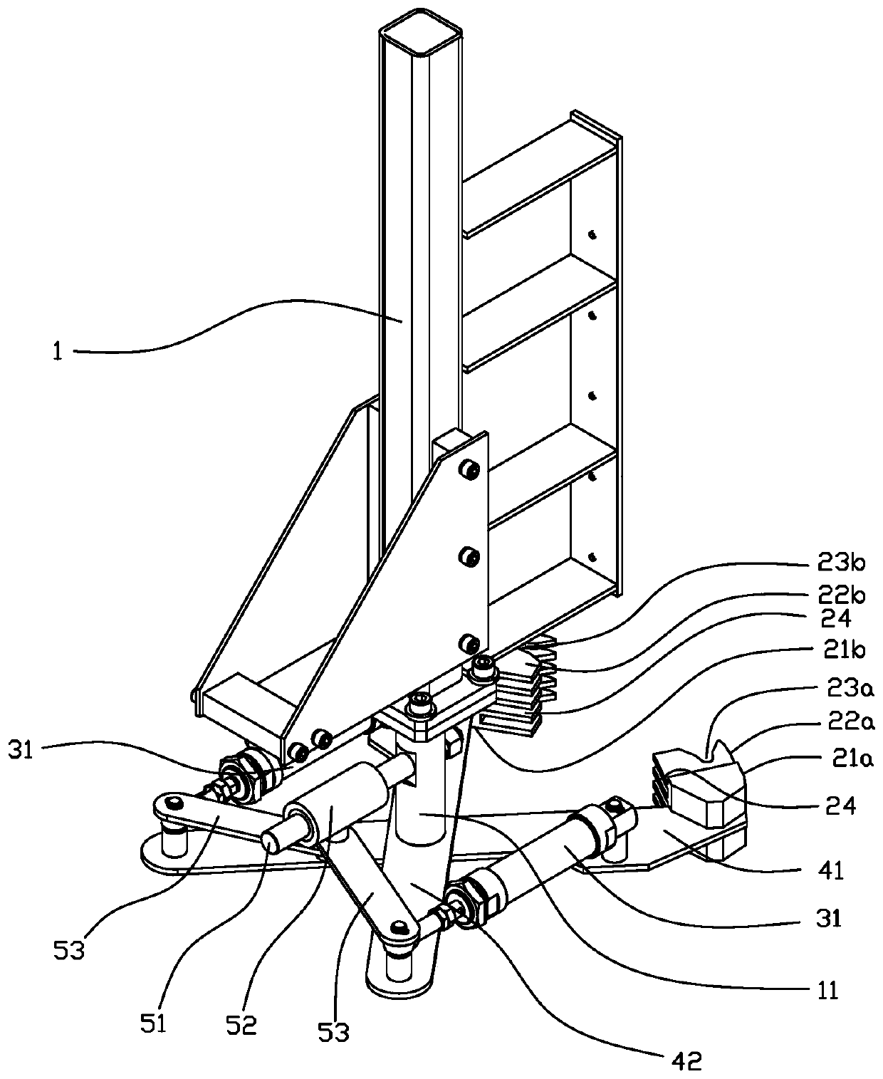
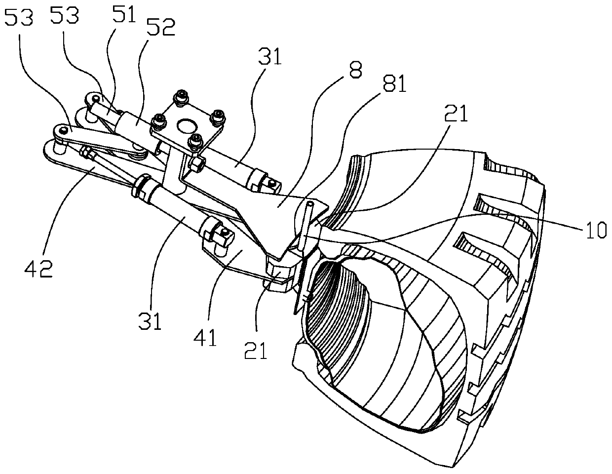
[0005] The present invention aims at the problems of cumbersome operation, high work intensity, poor clamping firmness of the clamping device and difficulty in realizing automatic inflation in the current manual inflation operation, and proposes a clamping device and an inflation device capable of firmly clamping the gas nozzle so as to realize automatic inflation

Method used


Image

  • Clamping device and inflating device
  • Clamping device and inflating device
  • Clamping device and inflating device

Examples


Embodiment Construction

[0042] In the following, the present invention will be specifically described through exemplary embodiments. It should be understood, however, that elements, structures and characteristics of one embodiment may be beneficially incorporated in other embodiments without further recitation.

[0043] In the description of the present invention, it should be noted that the orientation or positional relationship indicated by the terms "inner", "outer", "upper", "lower", "front", "rear" etc. are based on the The positional relationship is only for the convenience of describing the present invention and simplifying the description, but does not indicate or imply that the referred device or element must have a specific orientation, be constructed and operated in a specific orientation, and thus should not be construed as limiting the present invention. In addition, the terms "first", "second", and "third" are used for descriptive purposes only, and should not be construed as indicating...


PUM


Abstract

The invention discloses a clamping device and an inflating device. The clamping device comprises a bracket, a clamping assembly and a first driving unit; and the inflating device comprises the clamping device and further comprises an inflating unit, the inflating unit comprises a guiding rail, a fixed frame, an inflating joint and a second driving unit. According to the clamping device, through inserting connection of claw teeth on a clamping claw, the claw teeth are arranged in a staggered mode, a cylindrical gas nozzle is clamped, the number of clamping contact points is increased, the firmness of clamping the gas nozzle is improved, upward friction force of a gas nozzle shaft is increased, inserting connection of the inflating joint can be resisted, it is ensured that the inflating joint and the gas nozzle can be connected tightly, and thus smooth inflating is ensured. The inflating joint is guided by the guiding rail to rise and fall, thus the inflating joint can be automatically connected to the clamped and fixed gas nozzle in an inserted mode, an inner tube can be automatically inflated in the tire assembling process, the labor intensity of workers is reduced, and the overallspeed of tire assembly operation is increased.

Description

technical field [0001] The invention belongs to the technical field of mechanical equipment, and in particular relates to a clamping device and an inflating device. Background technique [0002] The produced tires need to be filled with inner tubes and pads, and then the tires are packed with packaging materials such as wrapping films and nylon belts, and finally stacked and stacked for transportation. In order to prevent the stacked tires from being flattened and causing the stacked tires to collapse, before the tires are packaged, a certain amount of gas needs to be filled into the inner tube to prop up the tires and maintain their shape. [0003] At present, manual operation is mainly used to inflate tires. The staff need to manually connect the air pump connector to the air nozzle of the inner tube, and then the air pump will fill the inner tube with gas. After the inflation is completed, the staff also need to manually remove the air pump connector from the inner tube. ...

Claims


Application Information

Patent Timeline
Patent Type & Authority Applications(China)
IPC IPC(8): B29D30/08
CPCB29D30/08
Inventor 孙贤功高玉国
Owner 青岛科力达机械制造有限公司
Learn More