
Steer-by-wire system

A technology of steer-by-wire and steering devices, applied to steering mechanisms, steering rods, mechanical steering mechanisms, etc., can solve problems such as inability to generate reaction force torque, and achieve the effect of ensuring operability and improving reliability

Inactive Publication Date: 2019-07-05
TOYOTA JIDOSHA KK
View PDF6 Cites 5 Cited by
  • Summary
  • Abstract
  • Description
  • Claims
  • Application Information

AI Technical Summary

Problems solved by technology

The action of the reaction motor is not controlled, so the reaction torque cannot be flexibly generated according to the operation of the steering wheel

Method used


Image

  • Steer-by-wire system
  • Steer-by-wire system
  • Steer-by-wire system

Examples


Embodiment Construction

[0066] Embodiments of the present invention will be described with reference to the drawings.

[0067] 1. Basic composition of steering-by-wire system

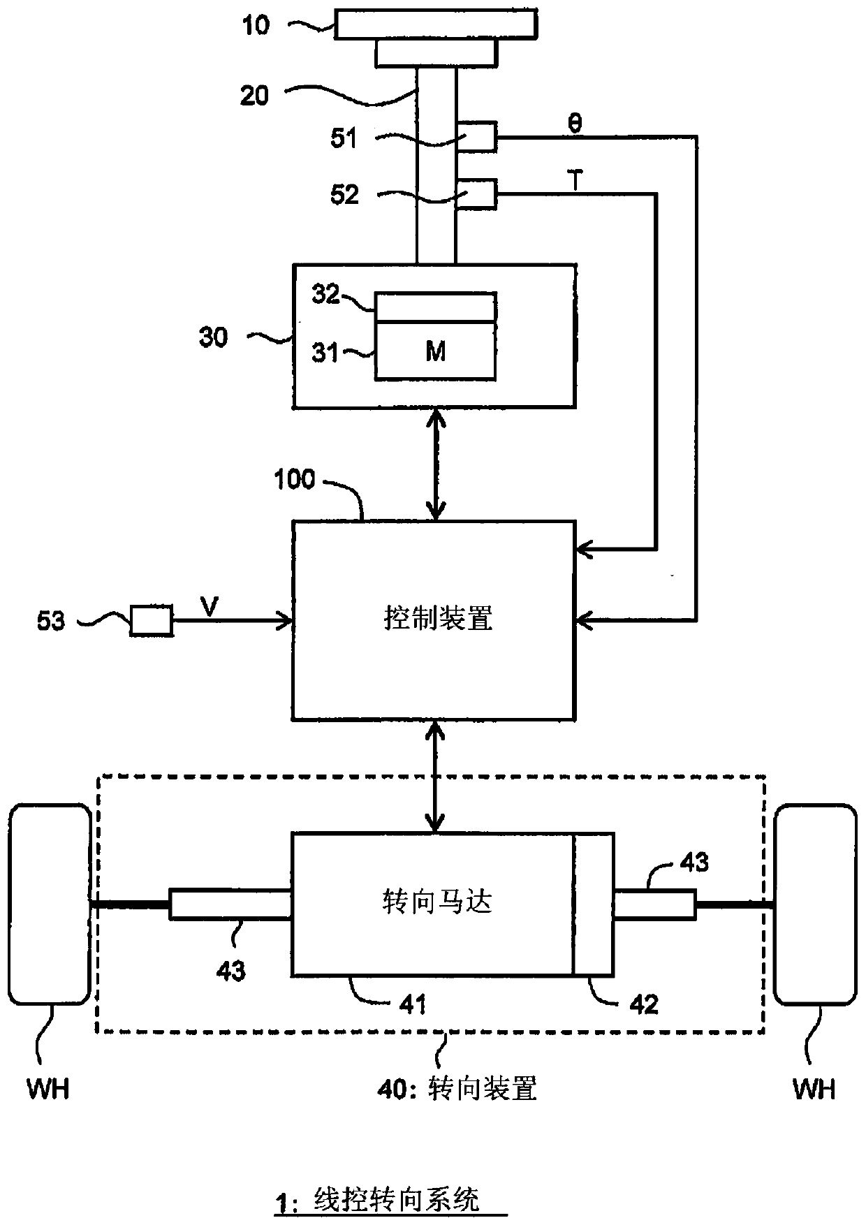
[0068] figure 1 It is a block diagram schematically showing a configuration example of the steer-by-wire system 1 according to the present embodiment. The steer-by-wire system 1 is mounted on a vehicle, and steers wheels WH of the vehicle by a steer-by-wire system. More specifically, the steer-by-wire system 1 includes a steering wheel 10 , a steering shaft 20 , a steering reaction force generating device 30 , a steering device 40 , a group of sensors ( 51 to 53 ), and a control device 100 .

[0069] A steering wheel 10 (steering wheel) is an operating member used by a driver for steering. The steering shaft 20 is connected to the steering wheel 10 and rotates together with the steering wheel 10 .

[0070] The steering reaction force generating device 30 simulates a reaction torque TR to the steering wheel 10 . Specifical...


PUM


Abstract

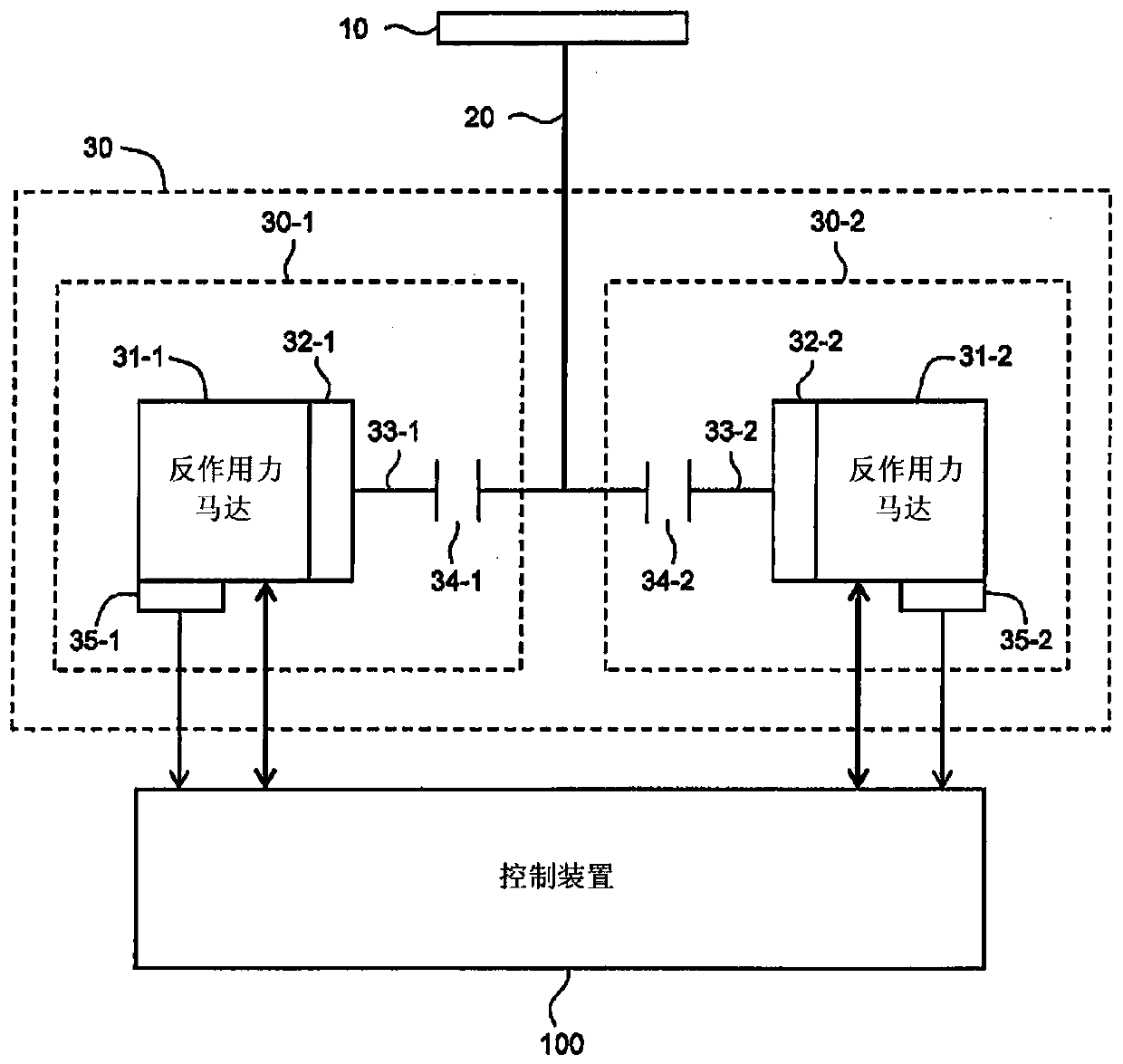
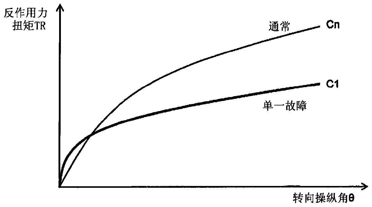
The invention relates to a steer-by-wire system capable of flexibly generating a reaction torque applied to a steering wheel even in the event of a failure of a reaction motor. A steering reaction force generating device that generates the reaction torque is doubled. The steering reaction force generating device includes a first system and a second system, each system including a reaction torque motor. A control device controls the action of the steering reaction force generating device in accordance with the operation of the steering wheel, thereby controlling the reaction torque. When both systems are normal, the control device generates the reaction torque having a normal characteristic by controlling an operation of the reaction torque motor of at least one system. In a case of singlefailure where one of the systems fails, the control device generates the reaction torque having a first characteristic by controlling an operation of the reaction torque motor of another of the systems. The reaction torque having the first characteristic is different from the reaction torque having the normal characteristic with respect to a same steering angle.

Description

technical field [0001] The present invention relates to steer-by-wire systems. Background technique [0002] A steer-by-wire (Steer-By-Wire) system vehicle is known. In the case of the steer-by-wire system, the steering mechanism that steers the wheels is mechanically separated from the steering wheel. Instead, an electric motor is provided in the steering mechanism. Steering is performed by driving the electric motor according to the operation of the steering wheel. On the other hand, a reaction motor (reaction actuator) is provided in order to give the driver a steering feel. By controlling the operation of the reaction motor according to the operation of the steering wheel, a reaction torque of a desired characteristic is applied to the steering wheel. [0003] Here, consider a case where the reaction force motor fails. If the reaction motor fails, the reaction torque felt by the driver becomes small, making it difficult for the driver to accurately control the steer...

Claims


Application Information

Patent Timeline
Patent Type & Authority Applications(China)
IPC IPC(8): B62D5/04B62D6/00B62D101/00B62D137/00
CPCB62D5/0463B62D6/001B62D6/008B62D5/006B62D5/0484B62D5/0421
Inventor 丹羽悟高岛亨守野哲也工藤佳夫
Owner TOYOTA JIDOSHA KK
Learn More