

Fuel cell device
- Summary
- Abstract
- Description
- Claims
- Application Information
AI Technical Summary
Benefits of technology
Problems solved by technology
Method used
Image

Examples
Embodiment Construction
[0049]Next, referring to the attached drawings, a solid oxide fuel cell (SOFC) device according to an embodiment of the present invention will be explained.
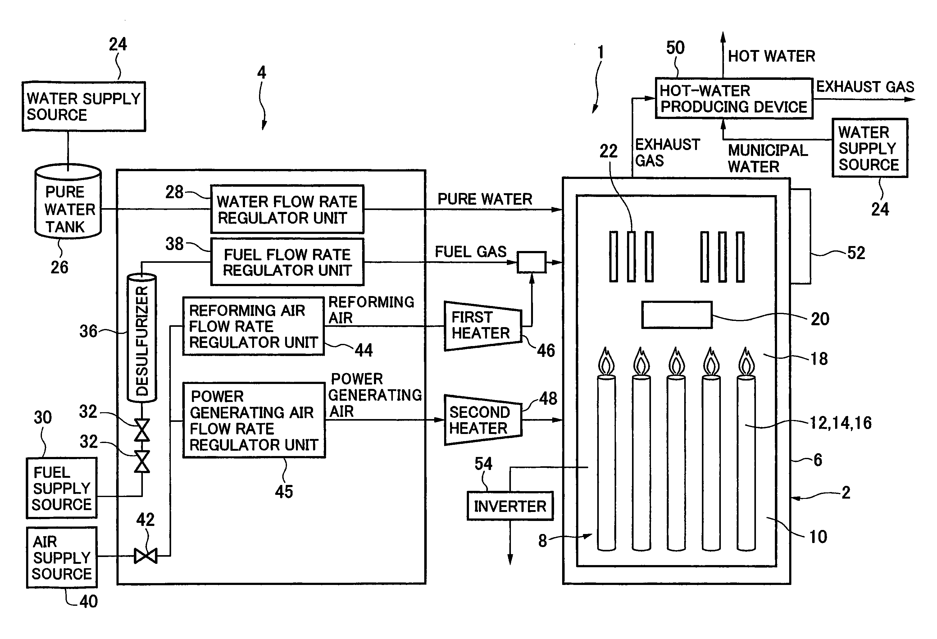
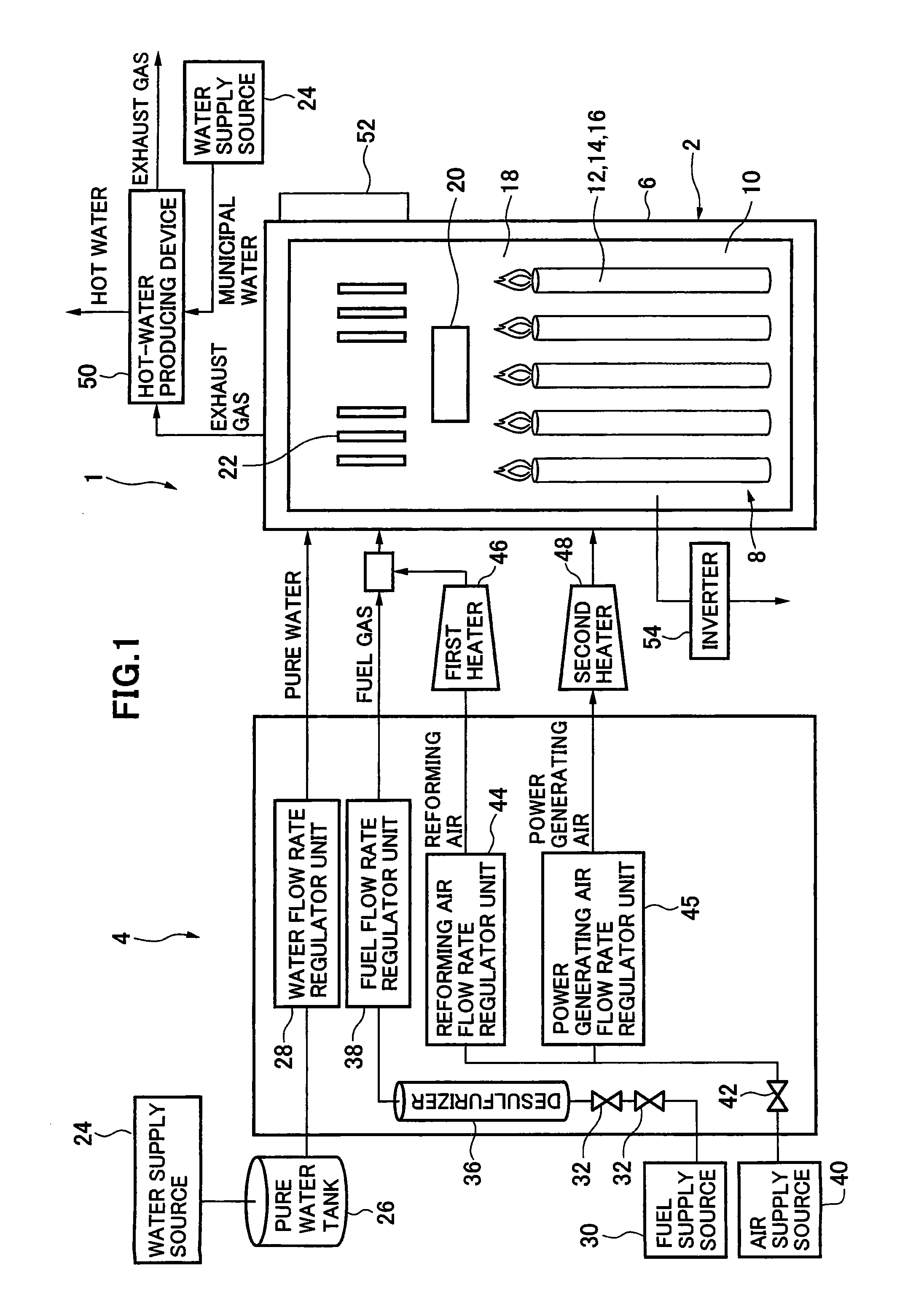
[0050]As shown in FIG. 1, a solid oxide fuel cell (SOFC) device according to an embodiment of the present invention is furnished with a fuel cell module 2 and an auxiliary unit 4.
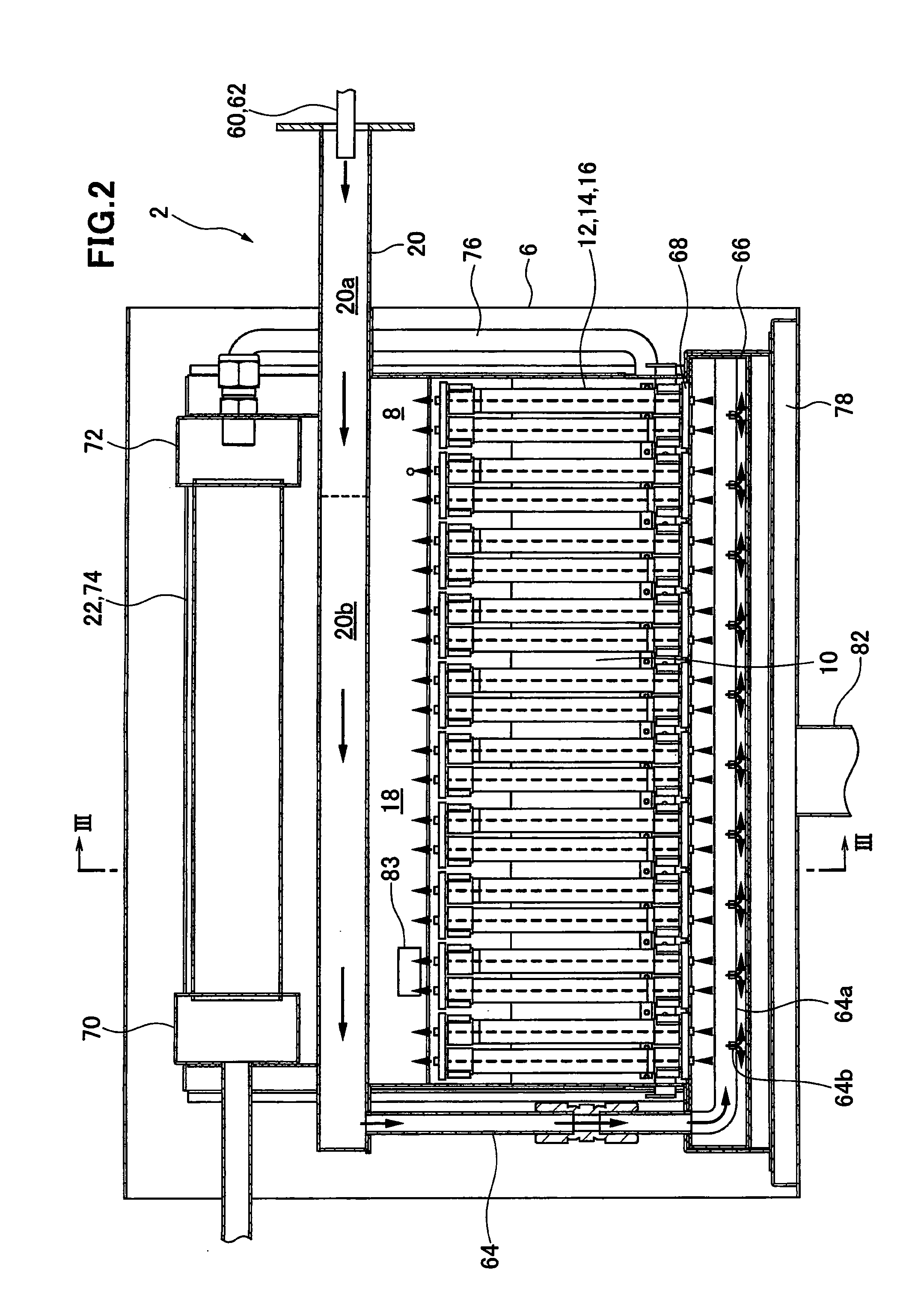
[0051]The fuel cell module 2 is furnished with a housing 6; a sealed space 8 is formed within the housing 6, mediated by insulating material (not shown, however the insulating material is not an indispensable structure and may be omitted). Note that it is acceptable to provide no insulating material. A fuel cell assembly 12 for carrying out the power generating reaction between fuel gas and oxidant (air) is disposed in the power generating chamber 10 at the lower portion of this sealed space 8. This fuel cell assembly 12 is furnished with ten fuel cell stacks 14 (see FIG. 5), and the fuel cell stack 14 comprises 16 fuel cell units 16 (see FIG. 4). Thus, ...
PUM
 Abstract
Description
Claims
Application Information