Electric oil pump assembly and vehicle with same
An electric oil pump and oil pump technology, which is applied to vehicle components, transportation and packaging, power steering mechanisms, etc., can solve the problems of high production cost, large installation space, and large installation space, and achieve short connection distance, compact structure, and low cost Effect
- Summary
- Abstract
- Description
- Claims
- Application Information
AI Technical Summary
Problems solved by technology
Method used
Image
Examples
Embodiment 1
[0204] refer to Figure 1-Figure 7 , The electric oil pump assembly 1000 includes a casing 21 , an oil pump assembly 1 and a motor assembly 2 .
[0205] In the first embodiment, the casing 21 is used to accommodate the oil pump assembly 1 and the motor assembly 2. The casing 21 defines an oil-filled assembly compartment 200. When the assembly compartment 200 includes a motor compartment 200A and an oil pump compartment 200B, the motor compartment 200A It is not directly connected with the oil pump compartment 200B through an oil hole or an oil passage, the motor assembly 2 is located in the motor compartment 200A, and the oil pump assembly 1 is located in the oil pump compartment 200B.
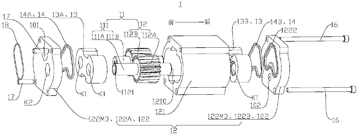
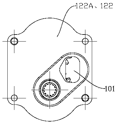
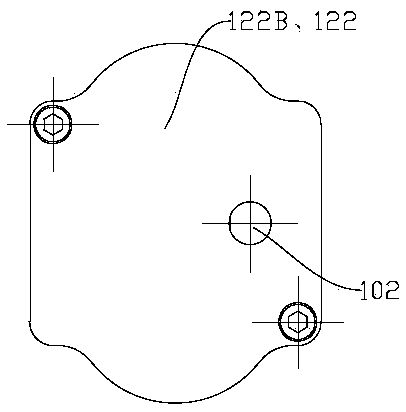
[0206] Such as Figure 1-Figure 5 As shown, the oil pump assembly 1 includes an oil pumping mechanism 11, a pump housing assembly 12, a bearing seat 13 and a sealing ring 14, wherein the oil pumping mechanism 11 includes a rotating shaft part 111 and an oil pumping part 112, wherein the rotat...
Embodiment 2
[0225] Such as Figure 8-Figure 14 As shown, the structure of this embodiment is substantially the same as that of Embodiment 1, wherein the same components use the same reference numerals, the difference is that: the drive shaft 24 is connected to the oil pump mechanism 11 in a different way, and the oil discharge of the oil pump assembly 1 Port 102 is set differently.
[0226] refer to Figure 8-Figure 14 , the drive shaft 24 is connected to the shaft portion 111 (such as the drive shaft 111A) of the oil pump mechanism 11 through a coupling 27 . Wherein, the coupling 27 can be a compact coupling (that is, a compact coupling), such as a slider type compact coupling, a joint type compact coupling, a gear type compact coupling device etc.
[0227] refer to Figure 8-Figure 14 The oil discharge ports 102 are multiple and distributed on the rear pump cover 122B at intervals along the circumferential direction of the oil pump part 112, and penetrate the peripheral wall of the ...
Embodiment 3
[0229] Such as Figure 15-Figure 21 As shown, the structure of the present embodiment is substantially the same as that of the second embodiment, wherein the same components use the same reference numerals, and the difference is that the front support scheme of the oil pump mechanism 11 is different.
[0230] refer to Figure 15-Figure 21 , the front side of the oil pump part 112 does not have the front bearing seat 13A, and the front pump cover 122A is replaced by a double bearing pump cover 122M2. Thus, the front end of the driving shaft 111A and the front end of the driven shaft 111B can be supported by the double bearing pump cover 122M2, so that the volume of the oil pump assembly 1 can be further reduced and the cost can be reduced.
PUM
 Abstract
Description
Claims
Application Information
 - R&D
- Intellectual Property
- Life Sciences
- Materials
- Tech Scout
- Unparalleled Data Quality
- Higher Quality Content
- 60% Fewer Hallucinations
Browse by: Latest US Patents, China's latest patents, Technical Efficacy Thesaurus, Application Domain, Technology Topic, Popular Technical Reports.
© 2025 PatSnap. All rights reserved.Legal|Privacy policy|Modern Slavery Act Transparency Statement|Sitemap|About US| Contact US: help@patsnap.com


