
Yarn dyeing device

A yarn dyeing and dyeing vat technology, applied in the field of dyeing devices, can solve the problems of poor yarn bulkiness and softness, increased yarn joints, and broken threads, etc., achieve good bulkiness and hand feeling, and increase weaving speed , to avoid the effect of yarn loss

Pending Publication Date: 2019-07-05
张家港市德胜染整有限责任公司
View PDF0 Cites 0 Cited by
  • Summary
  • Abstract
  • Description
  • Claims
  • Application Information

AI Technical Summary

Problems solved by technology

These three methods have disadvantages: the dyeing bath for tank dyeing is relatively large, usually around 1:20, and usually only some yarns with poor elasticity such as puffed yarns can be dyed, and the dyed yarns are easily messy and easy to break , easy to fluff; because it is necessary to turn the bobbin yarn into a hank yarn for dyeing, the hank yarn must be turned into a bobbin yarn after dyeing, which increases the intermediate link, thereby increasing the production cost and reducing the production efficiency. Moreover, the dyed There are rod marks in the yarn. In the process of converting the bobbin yarn into skein yarn and then from skein yarn to bobbin yarn, random yarn and thread breakage will inevitably occur, which will greatly increase the number of yarn joints. During the weaving process of sequence, it is easy to form holes
The yarn dyeing of the bobbin cylinder also has great limitations. It can only dye cotton yarn and solid acrylic yarn; moreover, the yarn dyed by bobbin cylinder dyeing has poor bulk and softness, which is sensitive to Colors such as army green, brown, etc. will also have a color difference between the inner layer and the outer layer
The disadvantages of yarn dyeing by jet cylinder are between the cabinet cylinder and the bobbin cylinder, and the dyed yarn also has disadvantages such as bad hand feeling, insufficient texture, easy to mess up and break, etc.

Method used


Image

  • Yarn dyeing device
  • Yarn dyeing device
  • Yarn dyeing device

Examples


Embodiment Construction

[0021] A specific embodiment of a yarn dyeing device according to the present invention will be described in detail below in conjunction with the accompanying drawings.

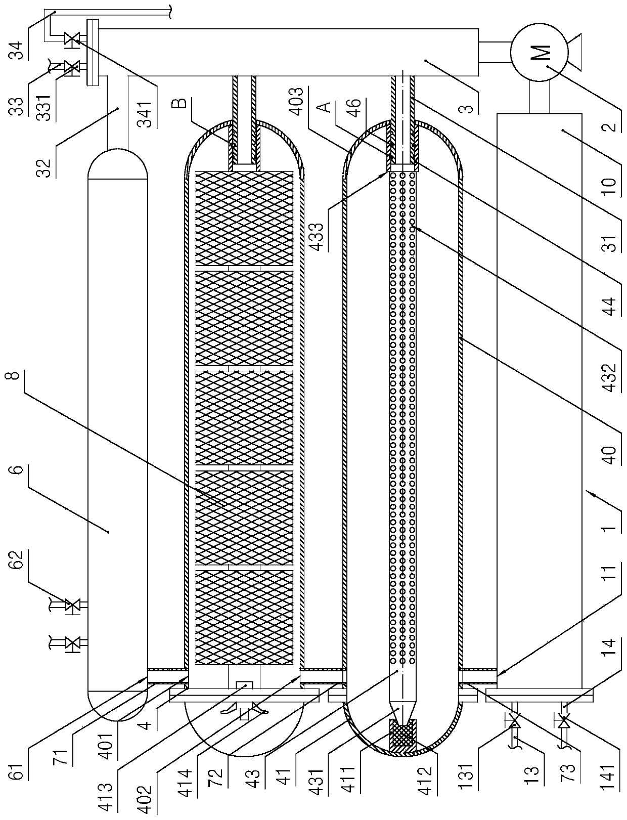
[0022] Such as figure 1 As shown, a kind of yarn dyeing device described in the present invention includes: frame (belonging to the common technology in this field, not shown in the figure) and circulation pump 2, on the frame from bottom to top is arranged in sequence along the horizontal Direction arranged heat exchanger 1, two dyeing vats 4 and buffer tank 6 (the quantity of dyeing vats 4 can be determined according to actual conditions), the concrete structure of described heat exchanger 1 comprises: heat exchange housing 10, and setting The spiral coil tube in the heat exchange housing 10 (belonging to the conventional technology in the art, not shown in the figure) and a pair of steam pipes pierced in the heat exchange housing 10, in the pair of steam pipes, as the A steam inlet control valve 131 is ar...


PUM


Abstract

The invention discloses a yarn dyeing device having the advantages that the bath ratio is low, the dyeing time is short, and disordered yarns, broken yarns, rod imprints and an uneven strip sense canbe avoided. The device comprises a rack and a circulating pump, a heat exchanger, dyeing cylinders and a buffering tank are arranged on the rack, and an inlet of the circulating pump is connected withan output port of the heat exchanger; an outlet of the circulating pump is connected with the dyeing cylinders and the buffering tank through an output pipeline, and the output pipeline comprises a main output pipe and output flow dividing pipes connecting the dyeing cylinders, the buffering tank and the main output pipe; a liquid inlet pipe is arranged on the main output pipe, and the top of themain output pipe is higher than the buffering tank and is provided with an overflow pipe; each dyeing cylinder comprises a dyeing cylinder body and a turnover cover, each dyeing cylinder body is internally provided with a yarn hanging pipe, a jet port is formed in each yarn hanging pipe, and blocking sealing mechanisms cooperating with the yarn hanging pipes are arranged on the turnover covers; abackflow passage is formed among the buffering tank, the dyeing cylinders and the thermal exchanger; a heating device is arranged in the heat exchanger. The above-mentioned yarn dyeing device can besuitable for various yarns.

Description

technical field [0001] The invention relates to a dyeing device used in the dyeing and finishing industry, in particular to a yarn dyeing device. Background technique [0002] At present, when dyeing yarn, there are no more than three methods, namely cabinet dyeing, bobbin dyeing and jet cylinder dyeing. These three methods have disadvantages: the dyeing bath for tank dyeing is relatively large, usually around 1:20, and usually only some yarns with poor elasticity such as puffed yarns can be dyed, and the dyed yarns are easily messy and easy to break , easy to fluff; because it is necessary to turn the bobbin yarn into a hank yarn for dyeing, the hank yarn must be turned into a bobbin yarn after dyeing, which increases the intermediate link, thereby increasing the production cost and reducing the production efficiency. Moreover, the dyed There are rod marks in the yarn. In the process of converting the bobbin yarn into skein yarn and then from skein yarn to bobbin yarn, ran...

Claims


Application Information

Patent Timeline
Patent Type & Authority Applications(China)
IPC IPC(8): D06B5/16D06B23/20D06B23/04
CPCD06B5/16D06B23/20D06B23/042
Inventor 林昌琦陈志良怀国华
Owner 张家港市德胜染整有限责任公司
Learn More