Shield simulation testing device with adjustable angle

A simulation test and shield technology, applied to teaching models, instruments, mining equipment, etc., can solve problems such as repeated disassembly, achieve the effect of simple operation platform, improve test efficiency, and simplify disassembly and assembly process

Active Publication Date: 2019-07-05
NORTHEASTERN UNIV
View PDF12 Cites 3 Cited by
  • Summary
  • Abstract
  • Description
  • Claims
  • Application Information

AI Technical Summary

Problems solved by technology

In recent years, when some scholars use traditional test devices to study the above problems, they order a large number of shield tunnel molds under different inclination angles. The test process needs to be disassembled repeatedly, which brings great inconvenience. The test device needs to be improved urgently.

Method used


Image

  • Shield simulation testing device with adjustable angle
  • Shield simulation testing device with adjustable angle
  • Shield simulation testing device with adjustable angle

Examples


Embodiment 1

[0044] An angle-adjustable shield simulation test device, which includes a model box, a shield tunnel mold, a piston baffle, a first tunnel mold fixing plate, a second tunnel mold fixing plate, a telescopic rod, a slot, a fixing rod and Buckle; wherein, the first tunnel mold fixing plate and the second tunnel mold fixing plate are respectively arranged above and below one side of the model box, and the shield tunnel mold is fixed on the first tunnel mold fixing plate and the second tunnel mold fixing In the middle of the plate, 5mm thick water-stop rubber is set on the lower edge surfaces of the first tunnel mold fixing plate and the second tunnel mold fixing plate. On the one hand, it is used to fix the shield tunnel mold. The fine sand in the box leaked out, and part of the shield tunnel mold was embedded in the model box. The shape of the shield tunnel mold is a semi-cylindrical body used to simulate the completed tunnel for shield construction. The card slot is set on the ...

Embodiment 2

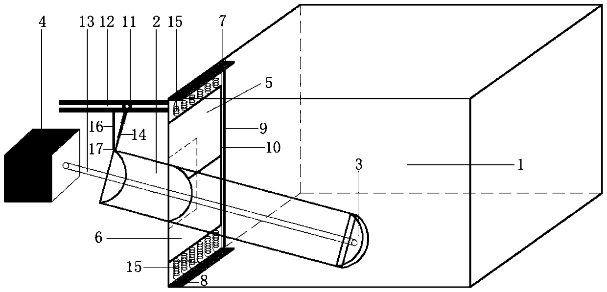
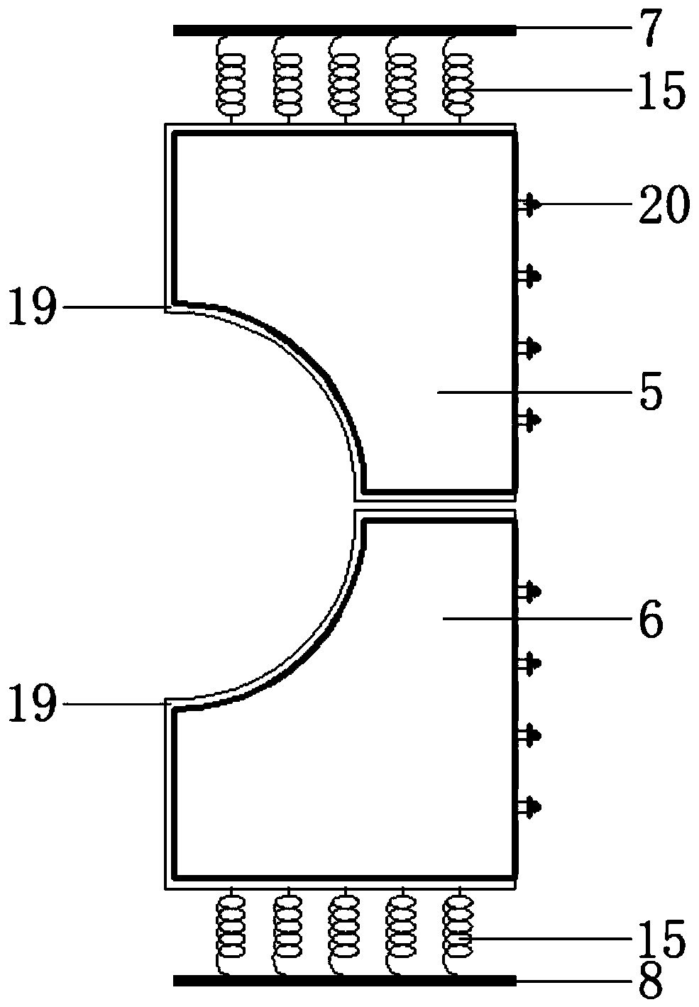
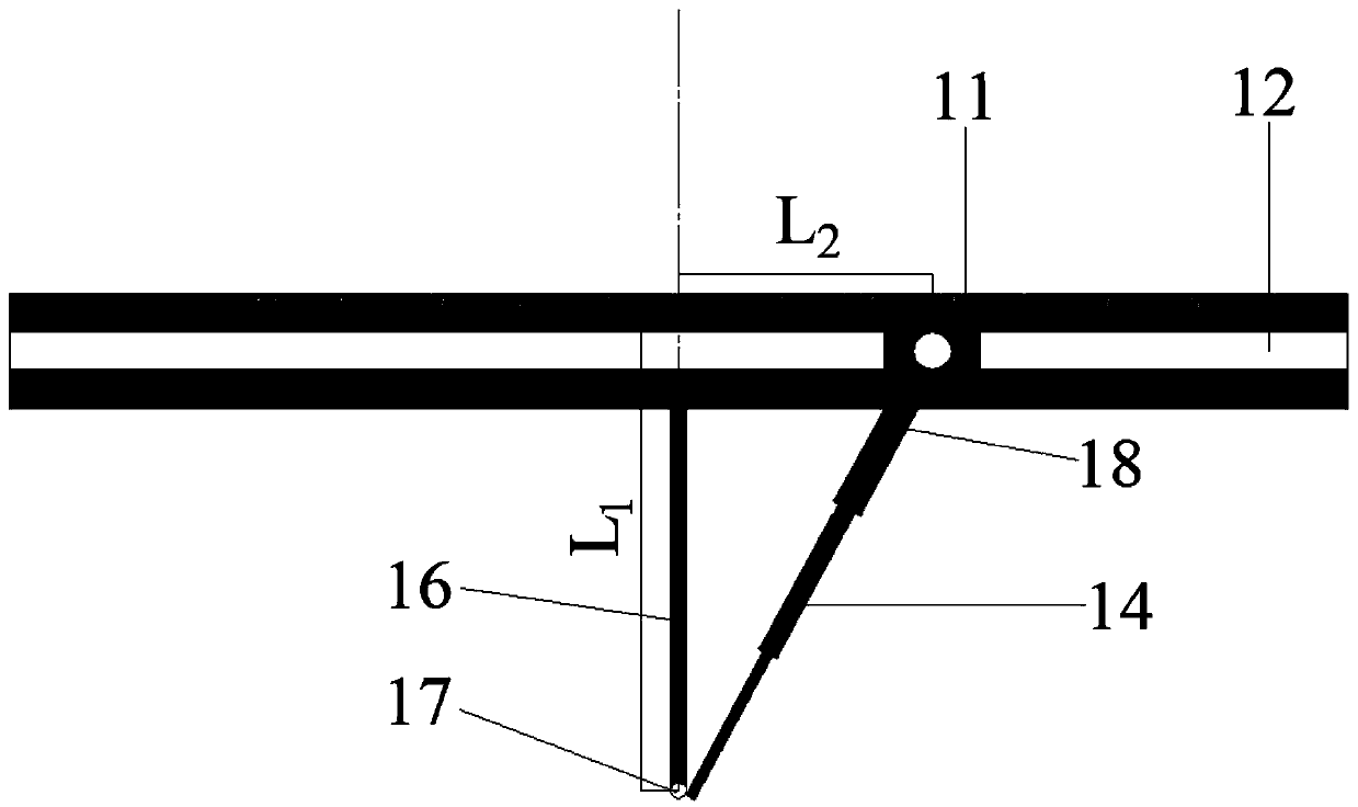
[0048] The shield simulation test device of the present embodiment is based on the embodiment 1, specifically as figure 1 As shown, it includes a model box 1, a shield tunnel mold 2, a piston baffle 3, a displacement controller 4, a first tunnel mold fixing plate 5, a second tunnel mold fixing plate 6, a buckle 11, a slot 12, Telescopic rod 14, fixed rod 16, spring 15 etc. The key components of the shield tunneling simulation experiment device are described in detail below:

[0049] Model box 1, its basic structure is a cubic box assembled by plexiglass plates around and at the bottom, and the top is exposed. The reserved size of the plexiglass plate on the side where the tunnel mold is installed is slightly larger than the hole of the shield tunnel mold;

[0050] Shield tunnel mold 2, its basic structure is a semi-cylindrical body made of Q235 steel, its cross-section is half a circle, placed close to the plexiglass, simulating the shield tunnel that has been built.

[0051] ...


PUM


Abstract

The invention relates to a shield simulation testing device with an adjustable angle. The shield simulation testing device comprises a model box, a shield tunnel mold, a first tunnel mold fixing plate, a second tunnel mold fixing plate, a telescopic rod, a clamping groove, a fixing rod and a buckle; the first tunnel mold fixing plate and the second tunnel mold fixing plate are arranged on the upper part and the lower part of one side face of the model box correspondingly, the shield tunnel mold is fixedly arranged between the first tunnel mold fixing plate and the second tunnel mold fixing plate, the clamping groove is horizontally formed in the outer side of the model box, one end of the fixing rod is perpendicularly and fixedly arranged on the clamping groove, the other end of the fixingrod is hinged to the end of the shield tunnel mold, the end of the shield tunnel mold is connected with one end of the telescopic rod, the other end of the telescopic rod is connected with the buckle, and the buckle is buckled in the clamping groove. According to the shield simulation testing device, the problems existing in a current device are effectively solved, the testing efficiency is significantly improved, and a simpler operation platform is provided for unstability simulation of the shield excavation surface.

Description

technical field [0001] The invention relates to an angle-adjustable shield tunneling simulation test device, which belongs to the technical field of subway tunnel shield construction and the field of geotechnical test devices. Background technique [0002] With the rapid development of social economy and the improvement of urbanization level, the rapid rise of urban subway has become an important means to relieve traffic pressure. The development and utilization of underground space has become a worldwide development trend. Traditional subway tunnel construction methods mainly include open cut method, new Austrian method, new Italian method and mining method. Among various subway tunnel construction methods, the shield method has the advantages of small impact on the surrounding environment, fast construction speed, mechanization and automation. The advantages of high degree of safety and high safety under complex geological conditions make it the preferred method for urban...

Claims


Application Information

Patent Timeline
Patent Type & Authority Applications(China)
IPC IPC(8): E21D9/093E21D9/087G09B25/04
CPCE21D9/087E21D9/093G09B25/04
Inventor 赵文程诚路博王云墨柏谦王志国李天亮
Owner NORTHEASTERN UNIV
Why Eureka
Try Eureka