Calibration system and calibration method for assisting laser osteotomy robots

A surgical robot and auxiliary laser technology, applied in the field of robot calibration, can solve problems such as complex operation process, dependence on measurement accuracy, and inability to meet clinical surgical requirements

Active Publication Date: 2019-07-05
SHANDONG UNIV
View PDF8 Cites 28 Cited by
  • Summary
  • Abstract
  • Description
  • Claims
  • Application Information

AI Technical Summary

Problems solved by technology

[0003] The inventor found in the research and development process that the traditional calibration method mostly relies on advanced measurement equipment, the calibration process is complicated, the cost of the measurement equipment is expensive, and the measurement accuracy largely depends on the accuracy of the measurement equipment, making it difficult to effectively apply in actual operation
However, the existing calibration methods relying on themselves, such as "four-point method" and "six-point method", have complicated operation processes and poor stability, which cannot meet the requirements of clinical operations.

Method used


Image

  • Calibration system and calibration method for assisting laser osteotomy robots
  • Calibration system and calibration method for assisting laser osteotomy robots
  • Calibration system and calibration method for assisting laser osteotomy robots

Examples


Embodiment 1

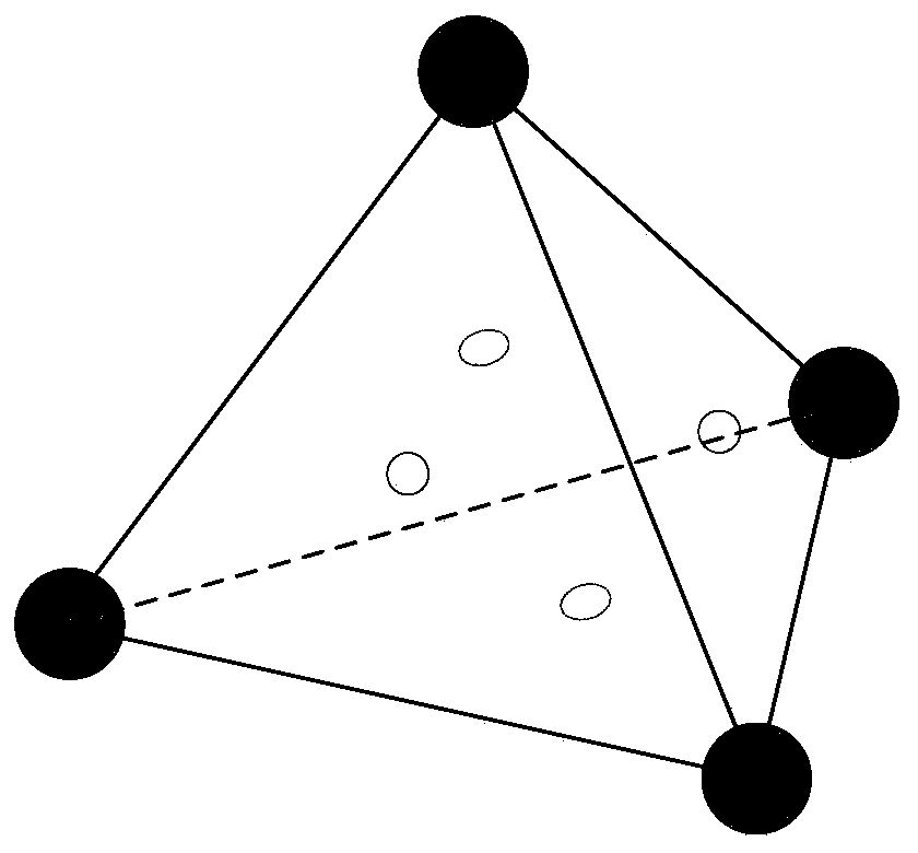
[0062] This embodiment provides a calibration system for an assisted laser osteotomy robot, the calibration device includes a robot system, a vision system, a calibration device and a processor, and the robot system adopts the existing technical structure of an assisted laser osteotomy robot system , which mainly includes a six-degree-of-freedom robot arm and a laser tool installed at the end of the robot arm. The vision system includes an infrared stereo camera, and the calibration device is a positive four-sided marker.

[0063] Please refer to the attached figure 1 , the calibration device is a positive four-sided marking body, tracking devices for infrared reflective balls are respectively installed at the four vertices of the positive four-sided marking body, and the four planes of the positive four-sided marking body are made of transparent materials respectively, so The central marking points of the four planes of the above-mentioned marking tool are respectively provi...

Embodiment 2

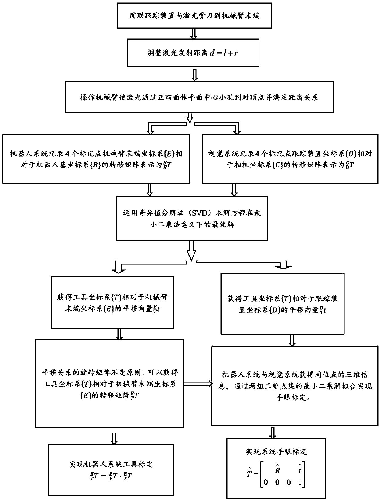
[0088] This embodiment provides a calibration method for an assisted laser osteotomy robot, which is implemented based on the calibration device for an assisted laser osteotomy robot as described above.

[0089] Please refer to the attached figure 2 , the calibration method of the auxiliary laser osteotomy robot comprises the following steps:

[0090] S101, setting a calibration body and a tracking device for an auxiliary laser osteotomy robot, and adjusting a laser emission distance.

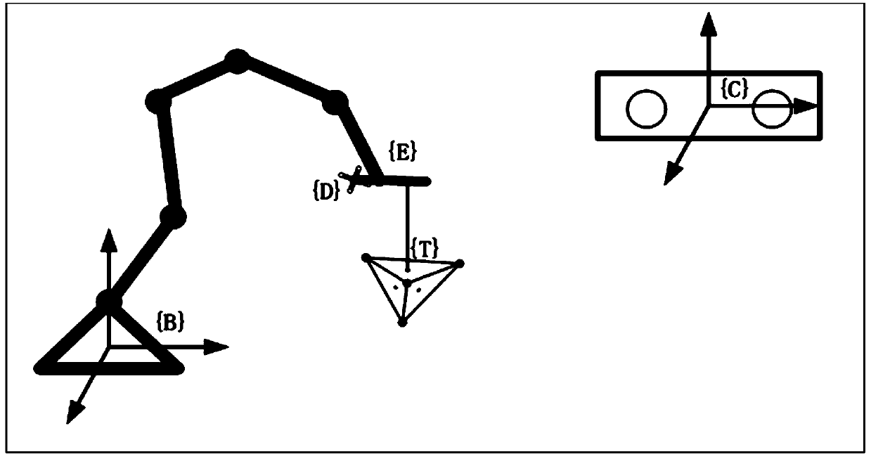
[0091]Let the robot base coordinate system be {B}, the robot end coordinate system be {E}, the camera coordinate system be {C}, the tracking device coordinate system be {D}, and the laser tool coordinate system be {T} (hereinafter referred to as tool coordinate system), {T} is the coordinate system established with the effective point of laser ablation as the origin, please refer to the attached image 3 .

[0092] Specifically, in the step 101, the specific implementation of adjusting the ...


PUM


Abstract

The invention discloses a calibration system and calibration method for assisting laser osteotomy robots. The method includes obtaining a transfer matrix of a mechanical arm end coordinate system relative to a robot base coordinate system and the transfer matrix of a tracking device coordinate system relative to a camera coordinate system; solving the translation vector of a tool coordinate systemrelative to the mechanical arm end coordinate system, and establishing the transfer matrix of the tool coordinate system relative to the mechanical arm end coordinate system; obtaining the transfer matrix of the tool coordinate system relative to the robot base coordinate system so that the tool calibration of a robot can be realized; and solving the translation vector of the tool coordinate system relative to the tracking device coordinate system, obtaining two sets of three-dimensional point sets of tool coordinate system original points, and solving the transfer matrix of the robot base coordinate system relative to the camera coordinate system so that the hand-eye calibration of the robot can be realized.

Description

technical field [0001] The present disclosure relates to the field of robot calibration, in particular to a calibration system and a calibration method for an auxiliary laser osteotomy robot. Background technique [0002] In recent years, surgical robot technology has been more and more widely used clinically. Assisted laser osteotomy robot is a task-autonomous surgical robot that can help doctors automatically complete osteotomy according to preoperative planning. Compared with traditional osteotomy instruments, it has the advantages of precise controllability and less damage to surrounding tissues. Tool calibration and hand-eye calibration are important steps before the installation and operation of the assisted osteotomy robot, which directly determine the positioning accuracy of the robot and the surgical effect. [0003] The inventor found in the research and development process that the traditional calibration method mostly relies on advanced measurement equipment, t...

Claims


Application Information

Patent Timeline
Patent Type & Authority Applications(China)
IPC IPC(8): G01B11/00G01B11/14A61B34/30
CPCA61B34/30A61B34/70G01B11/00G01B11/002G01B11/14
Inventor 宋锐王莉娟赵赫袁宏祥李倩倩
Owner SHANDONG UNIV
Why Eureka
Try Eureka