Automatic correction method and system for galvanometer marking of laser equipment

A laser equipment, automatic calibration technology, applied in optical instrument testing, machine/structural component testing, instruments, etc., can solve the problems of large subjective judgment errors, time-consuming and labor costs, etc., to avoid large judgment errors and reduce The effect of time cost and labor cost

Active Publication Date: 2022-04-05
HANS LASER TECH IND GRP CO LTD
View PDF10 Cites 0 Cited by
  • Summary
  • Abstract
  • Description
  • Claims
  • Application Information

AI Technical Summary

Problems solved by technology

[0005] The main purpose of the present invention is to provide a method and system for automatic calibration of galvanometer marks in laser equipment, aiming at solving the problem of using manual measurement for the calibration of marks in the prior art, which will lead to large subjective judgment errors, and will take a lot of time and labor. cost technical issues

Method used


Image

  • Automatic correction method and system for galvanometer marking of laser equipment
  • Automatic correction method and system for galvanometer marking of laser equipment
  • Automatic correction method and system for galvanometer marking of laser equipment

Examples


Embodiment Construction

[0022] In order to make the purpose, features and advantages of the present invention more obvious and understandable, the technical solutions in the embodiments of the present invention will be clearly and completely described below in conjunction with the accompanying drawings in the embodiments of the present invention. Obviously, the described The embodiments are only some of the embodiments of the present invention, but not all of them. Based on the embodiments of the present invention, all other embodiments obtained by those skilled in the art without making creative efforts belong to the protection scope of the present invention.

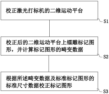
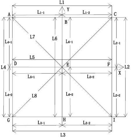
[0023] see figure 1 , is an automatic correction method for laser equipment galvanometer marking, including: S1, correcting the two-dimensional motion platform of the laser marking machine; S2, engraving the mark pattern on the two-dimensional control platform after correction, and calculating the mark figure Distortion data; S3. Correcting ...


PUM


Abstract

The invention discloses an automatic correction method and system for laser equipment galvanometer marking, which belongs to the field of laser equipment correction, and is used for automatic correction of marking graphics, solving the problem of subjective judgment errors caused by manual measurement of marking correction in the prior art Large, and it will take a lot of time and labor costs, including: correcting the two-dimensional motion platform of the laser marking machine; engraving marking graphics on the corrected two-dimensional control platform, and calculating the distortion data of the marking graphics; According to the standard size data of the distortion data and the standard mark figure, the mark figure is corrected; thereby the link of manually measuring the mark is eliminated, which not only avoids the occurrence of large subjective judgment errors caused by manual measurement, but also reduces the The time cost and labor cost of manually measuring the mark.

Description

technical field [0001] The invention relates to the field of laser equipment calibration, in particular to an automatic calibration method and system for laser equipment vibrating mirror marks. Background technique [0002] Laser marking machine is to use laser beam to make permanent marks on the surface of various materials, so as to carve exquisite patterns, trademarks or characters. [0003] During the use of the laser marking machine, the scanning lens will be concave or convex in the direction of the X-axis or Y-axis, or the mark will be trapezoidal or parallelogram due to the deviation of the installation position of the scanning galvanometer (standard The mark is a square), or due to the unevenness of the scanning lens and the nonlinearity of the scanning galvanometer, the size of the entire marking range is not uniform, which reduces the accuracy of the laser marking machine. [0004] The existing method of correcting marks is to import a square figure with a size o...

Claims


Application Information

Patent Timeline
Patent Type & Authority Patents(China)
IPC IPC(8): G01M11/04
CPCG01M11/00
Inventor 曹洪涛吕启涛杨柯刘振强高云峰
Owner HANS LASER TECH IND GRP CO LTD
Why Eureka
Try Eureka