Electric vehicle charging socket mounting structure

A charging socket and installation structure technology, applied in electric vehicle charging technology, electric vehicles, charging stations, etc., can solve the problems of inconvenient charging operation, large space occupation, small space occupation, etc., to achieve good strength and rigidity, and space occupation. Small, easy to charge and operate

Inactive Publication Date: 2019-07-05
ZHEJIANG LEAPMOTOR TECH CO LTD
View PDF8 Cites 3 Cited by
  • Summary
  • Abstract
  • Description
  • Claims
  • Application Information

AI Technical Summary

Problems solved by technology

[0002] Electric vehicles in China are equipped with charging sockets; national standard charging sockets are divided into fast charging sockets and slow charging sockets, European standard charging sockets are different in size from national standard charging sockets, and fast charging and slow charging are integrated in one integrated socket; traditional electric vehicles The slow charging socket is usually arranged on the front grille, the fast charging socket is usually arranged on the side wall, or the fast charging socket and the slow charging socket are arranged separately on both sides of the fender, which has the disadvantages of occupying a large space and inconvenient charging operation ; If the fast-charging socket and the slow-charging socket are arranged on the same side of the side wall, there is a problem that it is necessary to develop two kinds of wheel house outer panel molds, which are costly and cannot be applied to the installation of European standard integrated sockets at the same time; the side wall outer panel, There is no connection between the outer plates of the wheel house, which is prone to vibration; therefore, to design a fast charging socket and a slow charging socket to be arranged on the same side of the side wall, it is only necessary to develop a mold for the outer plate of the wheel house, and the cost is relatively low. It takes up less space and is easy to operate for charging. It can also be suitable for installing European standard integrated sockets. The installation structure of electric vehicle charging sockets with high connection strength between the side wall outer panel and the wheel house outer panel is not easy to generate vibration, and has become an urgent problem to be solved.

Method used


Image

  • Electric vehicle charging socket mounting structure
  • Electric vehicle charging socket mounting structure
  • Electric vehicle charging socket mounting structure

Examples


Embodiment 1

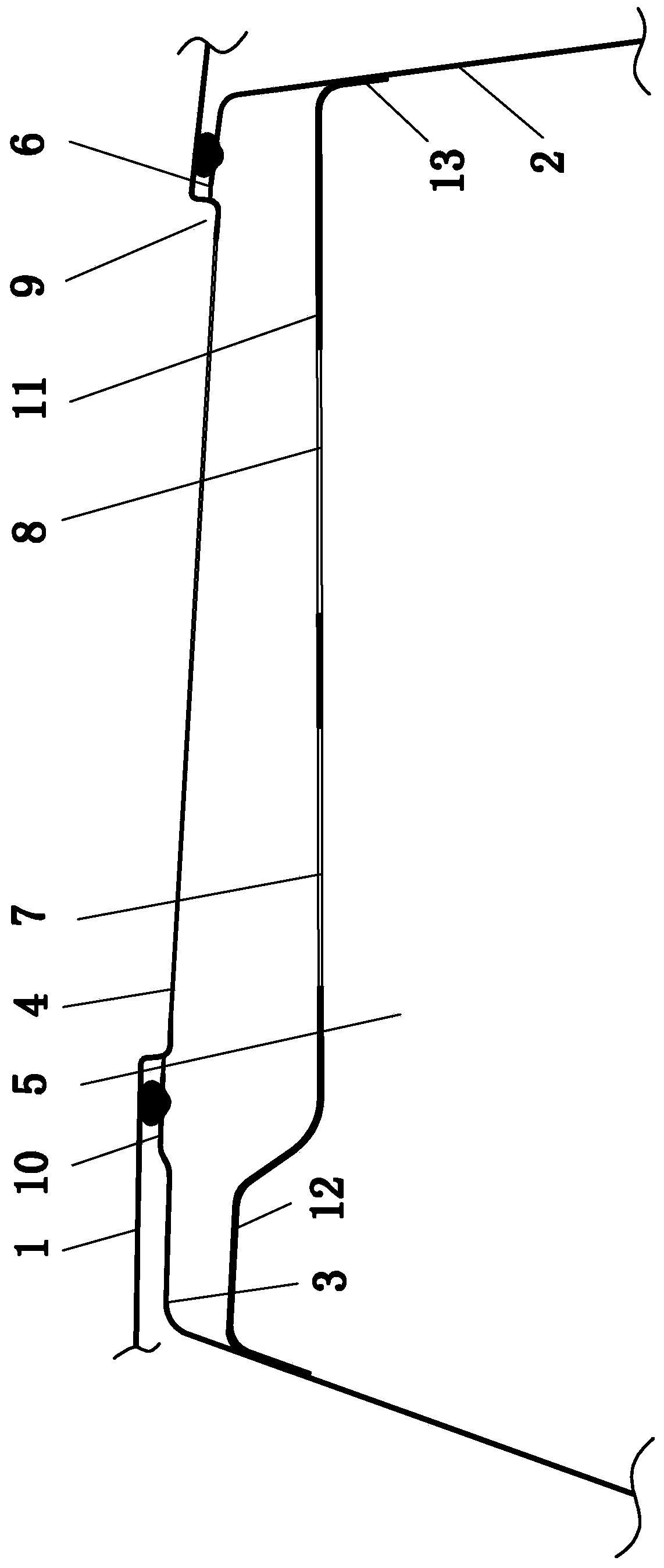
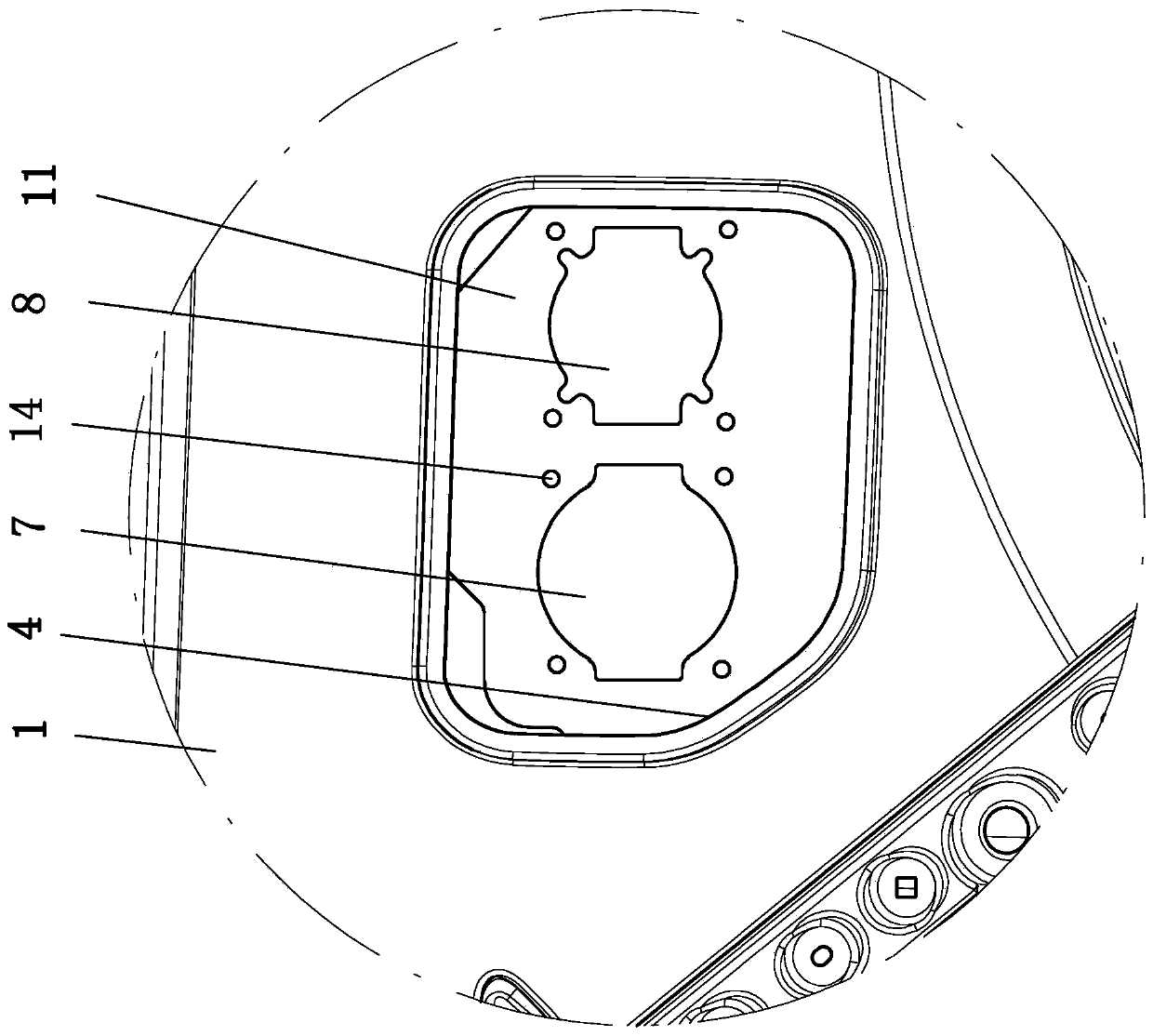
[0018] Example 1, such as figure 1 , figure 2 Shown: a charging socket installation structure for electric vehicles, including: a side wall outer plate 1, a wheel house outer plate 2, a boss 3 arranged at the outer end of the wheel house outer plate 2 and connected to the inner end of the side wall outer plate 1, The outer through hole 4 provided on the side wall outer panel 1, the counterbore 5 provided at the inner end of the boss 3, the inner through hole 6 provided at the bottom of the counterbore 5 and the outer end is opposite to the outer through hole 4, is provided with a quick charge Socket hole 7 and the charging socket bracket of slow charging socket hole 8; Charging socket bracket is connected with counterbore 5 inner sides and fast charging socket hole 7 and slow charging socket hole 8 are opposite to inner through hole 6 respectively.

[0019] The outer end of the side wall outer panel 1 is provided with a cover installation recess 9; the outer through hole 4 i...

Embodiment 2

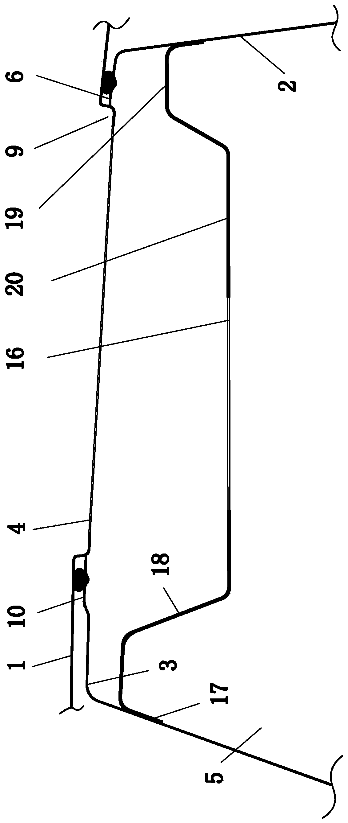
[0023] Example 2, such as image 3 , Figure 4 Shown: a charging socket installation structure for electric vehicles, including: a side wall outer plate 1, a wheel house outer plate 2, a boss 3 arranged at the outer end of the wheel house outer plate 2 and connected to the inner end of the side wall outer plate 1, The outer through hole 4 provided on the side wall outer panel 1, the counterbore 5 provided at the inner end of the boss 3, the inner through hole 6 provided at the bottom of the counterbore 5 and the outer end is opposite to the outer through hole 4, and an integrated socket is provided The integrated socket bracket of the hole 16;

[0024] The outer end of the side wall outer panel 1 is provided with a cover installation recess 9; the outer through hole 4 is located on the bottom surface of the cover installation recess 9.

[0025] In this example:

[0026] The outer end of the boss 3 is provided with a protruding ring 10 sleeved outside the inner through hole ...


PUM


Abstract

The invention relates to an electric vehicle charging socket mounting structure, comprising a side wall outer plate, a wheel cover outer plate, a boss disposed on the outer end of the wheel cover outer plate and connected to the inner end of the side wall outer plate, an outer through hole disposed on the side wall outer plate, a counterbore disposed on the inner end of the boss, an inner throughhole disposed on the bottom surface of the counterbore and opposite to the outer through hole, a charging socket bracket having a fast charging socket hole and a slow charging socket hole, and an integrated socket bracket having integrated socket jacks, wherein the charging socket bracket is connected to the inner side wall of the counterbore, or the integrated socket bracket is connected to the inner side wall of the counterbore. The fast charging socket and the slow charging socket of the electric vehicle charging socket mounting structure are arranged on the same side of the side wall so asto achieve low mold cost, small occupied space, and convenient charging operation. Further, the electric vehicle charging socket mounting structure can be used for mounting a European standard integrated socket. The side wall outer plate and the wheel cover outer plate has high connection strength and are less likely to vibrate.

Description

technical field [0001] The invention relates to the field of motor manufacturing, in particular to an electric vehicle charging socket installation structure. Background technique [0002] Electric vehicles in China are equipped with charging sockets; national standard charging sockets are divided into fast charging sockets and slow charging sockets, European standard charging sockets are different in size from national standard charging sockets, and fast charging and slow charging are integrated in one integrated socket; traditional electric vehicles The slow charging socket is usually arranged on the front grille, the fast charging socket is usually arranged on the side wall, or the fast charging socket and the slow charging socket are arranged separately on both sides of the fender, which has the disadvantages of occupying a large space and inconvenient charging operation ; If the fast-charging socket and the slow-charging socket are arranged on the same side of the side ...

Claims


Application Information

Patent Timeline
Patent Type & Authority Applications(China)
IPC IPC(8): H01R13/74H01R13/52H01R13/502H01R27/00B60L53/16
CPCH01R13/502H01R13/5213H01R13/748H01R27/00H01R2201/26Y02T10/70Y02T10/7072Y02T90/14
Inventor 李河河刘建胜刘胜甲郭大洲
Owner ZHEJIANG LEAPMOTOR TECH CO LTD
Why Eureka
Try Eureka