Silicon wafer worktable for LED chip automatic sorting machine

A workbench and sorter technology, applied in workbenches, sorting, manufacturing tools, etc., can solve the problems of slow action execution, inconvenient installation and adjustment, low slip accuracy, etc., to facilitate installation and improve debugging efficiency. Effect

Pending Publication Date: 2019-07-09
山东泓瑞光电科技有限公司
View PDF0 Cites 1 Cited by
  • Summary
  • Abstract
  • Description
  • Claims
  • Application Information

AI Technical Summary

Problems solved by technology

[0002] Due to the limitation of its structure, the traditional silicon wafer workbench has low sliding precision, slow action execution, and the reliability cannot be controlled very effectively. The traditional workbench uses the origina

Method used


Image

  • Silicon wafer worktable for LED chip automatic sorting machine
  • Silicon wafer worktable for LED chip automatic sorting machine
  • Silicon wafer worktable for LED chip automatic sorting machine

Examples


Embodiment Construction

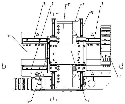
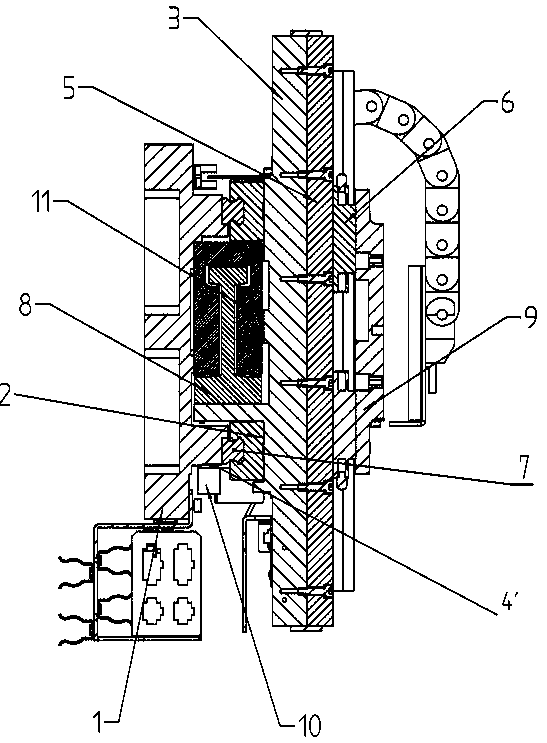
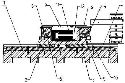
[0019] Examples, as attached figure 1 , attached figure 2 And attached image 3 As shown, a silicon wafer workbench for an automatic LED wafer sorting machine includes an X-axis workbench 1, an X-axis guide rail 7 is arranged on the X-axis workbench 1, and an X-axis guide rail 7 is provided to slide along the X-axis guide rail 7. X-axis guide rail slider 2.

[0020] It also includes a Y-axis workbench 3, which is arranged above the X-axis workbench 1, the Y-axis workbench 3 can slide relative to the X-axis workbench 1, and the Y-axis workbench 3 is fixedly connected with a guide rail slider 2 , connect the Y-axis table 3 to the X-axis table 1 through the X-axis guide rail slider 2 .

[0021] The Y-axis workbench 3 is provided with a Y-axis guide rail 5, and the Y-axis guide rail 5 is fastened on the Y-axis workbench 3, and the top workbench 9 is connected with the Y-axis workbench 3 by the guide rail slider 6.

[0022] Both the X-axis workbench 1 and the Y-axis workbench ...


PUM


Abstract

The invention discloses a silicon wafer worktable for an LED chip automatic sorting machine. The silicon wafer worktable comprises an X-axis worktable and a Y-axis worktable, wherein an X-axis guide rail is arranged on the X-axis worktable; the X-axis guide rail is provided with an X-axis guide rail sliding block capable of sliding along the X-axis guide rail; the Y-axis worktable is arranged at the upper portion of the X-axis worktable; the Y-axis worktable can slide relative to the X-axis worktable; the Y-axis worktable is fixedly connected with the guide rail sliding block; and the Y-axis worktable is connected with the X-axis worktable through the X-axis guide rail sliding block.

Description

technical field [0001] The invention relates to an automatic sorting machine for LED chips, in particular to a silicon wafer workbench for an automatic sorting machine for LED chips, and belongs to the technical field of LED chip manufacturing. Background technique [0002] Due to the limitation of its structure, the traditional silicon wafer workbench has low sliding precision, slow action execution, and the reliability cannot be controlled very effectively. The traditional workbench uses the original glass grating, which is inconvenient to install and adjust. , the debugging efficiency of the debugging process is low; and the glass grating is inconvenient to install, and the installation gap must be controlled during installation. Contents of the invention [0003] The technical problem to be solved by the present invention is to provide a silicon wafer workbench for an automatic LED wafer sorting machine in view of the above situation. The silicon wafer workbench has hi...

Claims


Application Information

Patent Timeline
IPC IPC(8): B07C5/00B25H1/00
CPCB07C5/00B25H1/00
Inventor 陈国强董月宁代立民
Owner 山东泓瑞光电科技有限公司
Why Eureka
Try Eureka