A bending device for hardware processing

A bending device and hardware technology, applied in the field of hardware processing, can solve the problems of inability to adjust the bending angle, small angle adjustment range, inaccurate bending angle, etc., achieve fast adjustment speed, large adjustment range, and easy replacement or the effect of overhaul

Inactive Publication Date: 2021-03-23
广州鸿志汽车配件有限公司
View PDF11 Cites 1 Cited by
  • Summary
  • Abstract
  • Description
  • Claims
  • Application Information

AI Technical Summary

Problems solved by technology

[0002] Hardware refers to tools obtained by processing gold, silver, copper, iron, tin and other metals. When the hardware is bent into a certain angle (that is, has a specific bending angle) by an external tool, due to the hardware itself If it is elastic, it may rebound under the action of its own elastic recovery force, resulting in inaccurate bending angles
[0004] However, in actual use, there are still many shortcomings. For example, the bending angle cannot be adjusted according to specific needs when the equipment is used in practice, and the adjustment range of the angle is small, which affects the solution to the problem of bending springback.

Method used


Image

  • A bending device for hardware processing
  • A bending device for hardware processing
  • A bending device for hardware processing

Examples


Embodiment 1

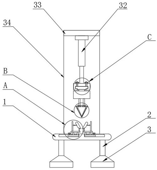
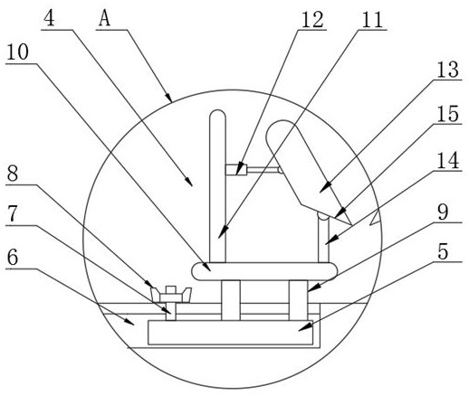
[0025] The present invention provides such as Figure 1-5 The shown bending device for hardware processing includes a bottom plate 1, the bottom of the bottom plate 1 is fixed with a support leg 2, and the bottom of the support leg 2 is fixed with a bottom pad 3, and the bottom pad 3 is formed by Made of rubber material, the surface of the bottom plate 1 is provided with two bottom mold angle adjustment devices 4, the two bottom mold angle adjustment devices 4 are relatively arranged at the center of the bottom plate 1, and the bottom mold angle adjustment device 4 includes a slider 5. The surface of the bottom plate 1 is provided with a chute 6, the slider 5 is slidably connected with the chute 6, the top of the slider 5 is provided with a screw 7, and the outer side of the screw 7 is provided with a wing nut 8, the The wing nut 8 is threadedly connected with the screw rod 7, and the slide block 5 is fixedly provided with a fixed rod 9 on one side of the screw rod 7, and the ...

Embodiment 2

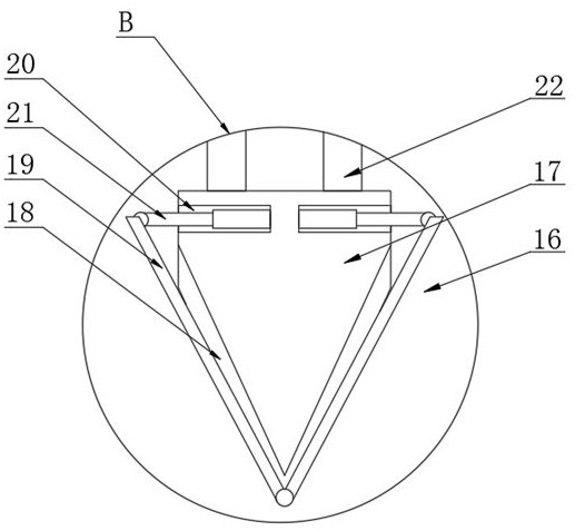
[0028] Further, a stamping device 16 is provided above the adjusting bottom template 13, and the stamping device 16 includes a stamping block 17, grooves 18 are provided on both sides of the bottom of the stamping block 17, and grooves 18 are arranged inside the groove 18. Stamping plate 19, the stamping plate 19 is matched with the groove 18, and the surface of both sides of the stamping block 17 is provided with placement grooves 20.

[0029] Further, the top of the stamping plate 19 is provided with a second hydraulic rod 21, the output shaft of the second hydraulic rod 21 is hinged to the top of the stamping plate 19, the bottom end of the stamping plate 19 is hinged to the inner wall of the groove 18, and the first Two hydraulic rods 21 are arranged inside the placing groove 20 .

[0030] Further, the top of the stamping block 17 is fixed with a connecting rod 22 , and the top of the connecting rod 22 is fixed with a top block 23 .

[0031] Further, the top of the top bl...


PUM


Abstract

The invention discloses a bending device for hardware processing, and particularly relates to the field of hardware processing. The bending device comprises a bottom plate, supporting legs are fixedlyarranged at the bottom of the bottom plate, a bottom cushion is fixedly arranged at the bottoms of the supporting legs, the bottom cushion is made of a rubber material, two bottom die angle adjustingdevices are arranged on the surface of the bottom plate, and the two bottom die angle adjusting devices are oppositely arranged in the center of the bottom plate; and each bottom die angle adjustingdevice comprises a sliding block, a sliding groove is formed in the surface of the bottom plate, the sliding blocks are in sliding connection with the sliding groove, the top of each sliding block isprovided with a screw rod, the outer side of each screw rod is provided with a butterfly nut, and the butterfly nut is in threaded connection with the corresponding screw rod. According to the bendingdevice for hardware processing, the bottom die angle adjusting devices are arranged, two adjusting bottom templates are in contact, so that the required angle is formed, then the bending angle can beadjusted according to needs, the adjustable amplitude is large, the adjusting speed is high, and the problem of bending resilience can be conveniently and quickly solved.

Description

technical field [0001] The invention relates to the technical field of hardware processing, and more specifically, the invention relates to a bending device for hardware processing. Background technique [0002] Hardware refers to tools obtained by processing gold, silver, copper, iron, tin and other metals. When the hardware is bent into a certain angle (that is, has a specific bending angle) by an external tool, due to the hardware itself If it is elastic, it may rebound under the action of its own elastic recovery force, resulting in inaccurate bending angles. [0003] The utility model patent of the patent application publication number CN207479341U discloses a metal stamping die structure with an adjustable bending angle, including a bending insert, an elbow swing block, a bending support block, an upper die and a lower die, and the upper die includes an upper die Die base, upper backing plate, fixing plate, stripping backing plate, stripping plate, the fixing plate is...

Claims


Application Information

Patent Timeline
Patent Type & Authority Patents(China)
IPC IPC(8): B21D11/00B21D11/22
CPCB21D11/00B21D11/22
Inventor 邓业泉
Owner 广州鸿志汽车配件有限公司
Why Eureka
Try Eureka