

Tool and method for machining microchannel structure at outlet end of inner bolt of engine injector
A processing method and injector technology, which are applied in electric processing equipment, metal processing equipment, manufacturing tools, etc., can solve the difficulty of clamping, difficult to meet the requirements of parts, and difficult to ensure the consistency of uniform micro-grooves to ensure design requirements, etc. problems, to ensure the dimensional accuracy and roughness requirements, to ensure the consistency of size and position, and to improve the effect of positioning accuracy
Active Publication Date: 2019-07-09
BEIJING INST OF CONTROL ENG
View PDF7 Cites 1 Cited by
- Summary
- Abstract
- Description
- Claims
- Application Information
AI Technical Summary
Problems solved by technology
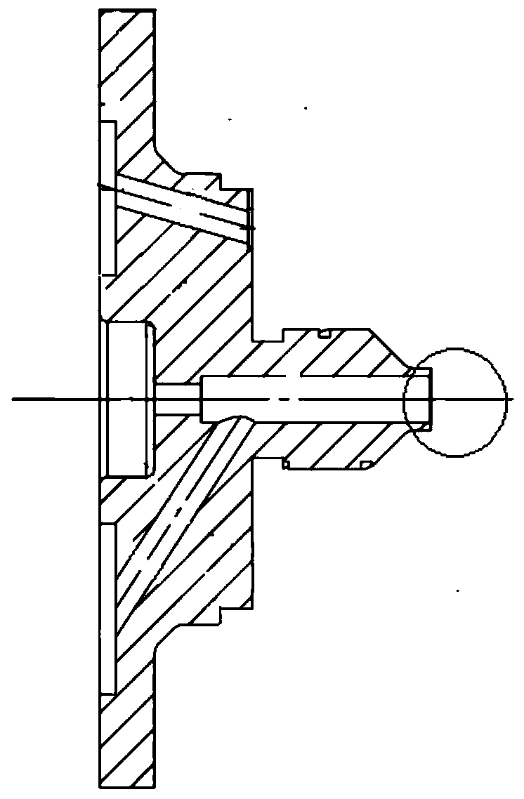
At present, the precision machining methods for the micro-groove structure mainly include cutting and wire-cutting, but the cutting process is limited by the high-precision size and high-position requirements of the micro-groove structure, and it is difficult to meet the requirements of the parts. Wire-cut processing is based on its Non-contact processing has the advantages of no obvious macro stress, small size processing and high positioning accuracy, and can realize the precision processing of high-density micro-grooves. However, because the flange of the inner bolt part has a square structure, it is very difficult to accurately position and clamp. At the same time, There are also many factors that affect wire cutting processing. Improper alignment methods and electrical processing parameters will cause the size uniformity and surface finish of the high-density symmetrical micro-groove structure to be difficult to meet the requirements.
At the same time, there are a total of 36 micro-groove structures in the injector, which require up to 18 repeated flips. During the processing, it is easy to accumulate clamping and positioning errors. It is difficult to ensure the consistency of uniformly distributed micro-grooves. Therefore, it is necessary to Using a dedicated method to ensure the area and position of multiple microgroove structures
Method used
View moreImage
Smart ImageViewing Examples

Examples
Embodiment
[0057] Use the designed special tooling to clamp the inner bolt parts, the wire cutting machine tool is used to align the outer circle of the inner bolt to 0.01mm, and the electrode wire is aligned to 0.003mm. The wire cutting processing parameters are designed as follows: electrode polarity, positive polarity; discharge waveform , rectangle; pulse width, 2μs; pulse interval, 18μs; wire speed: 2m / s; feed rate: 1; peak current, 1A.
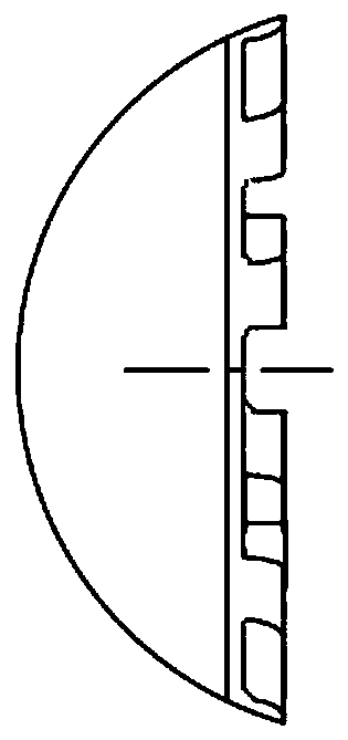
[0058] Implementation effect: The dimensional accuracy and consistency of the microgroove structure of the 36 internal bolt parts processed under the high-magnification imager are relatively good.
Login to View More PUM
 Abstract
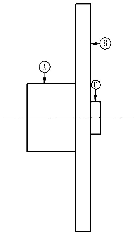
The invention relates to a tool and method for machining a microchannel structure at the outlet end of an inner bolt of an engine injector. The method comprises the steps of designing a clamping toolwhich facilitates clamping of a linear cutting machine and meanwhile is capable of ensuring accurate location of an inner bolt part, and then precisely aligning an inner bolt clamped on the tool through online cutting equipment; next, precisely aligning the initial position of an electrode wire according to the position of microchannel structures to be machined, and setting electrical machining parameters for machining the first pair of microchannel structures; and finally performing precise alignment during machining of subsequent microchannel structures repeatedly. The tool comprises a cylindrical aligning part of which the both sides are each provided with a boss, wherein the boss on one side of the cylindrical aligning part is regarded as a clamping part clamped on the online cutting equipment; the boss on the other side of the cylindrical aligning part is regarded as a locating part, and the outside surface of the locating part is in close fit with a central concave hole of a mounting flange; the clamping part, the aligning part and the locating part are coaxial, and the bottom surface of the aligning part is perpendicular to the cylindrical surface of the clamping part. According to the tool and method, the machining problem of high precision requirements of the inner bolt outlet structure in the injector is solved.
Description
technical field [0001] The invention relates to the technical field of special processing, in particular to a precision processing method for a high-density symmetrical micro-groove structure of an injector. Background technique [0002] In the field of aerospace, the pintle injector is a common injector mode, and the outlet structure of the inner plug part in the injector directly determines the control of the flow rate and uniformity. In order to achieve the purpose of precise flow control, a newly developed engine injector adopts the combination of high-density symmetrical micro-groove structure + annular seam for the first time, and the outlet end of the inner plug contains 36 (a total of 18) Right) micro-groove structure, its size is small (depth 0.14mm, width 0.3mm), high precision requirements, and the consistency and position of the micro-groove are extremely demanding, the area and position of the micro-groove structure directly affect the flow rate of the injector ...
Claims
Login to View More Application Information
Patent Timeline
 Patent Type & AuthorityApplications(China)
IPC IPC(8): B23H7/02B23H9/00
CPCB23H7/02B23H9/00B23H2500/20
Inventor杨春雷汪凤山申坤张志伟赵连清武胜勇黎月明陈曦李海明牛少鹏李晋军张林尹兆刚陈颖李桐
OwnerBEIJING INST OF CONTROL ENG