
Special device for multi-group wire-electrode cutting

A special device and wire cutting technology, which is applied in the direction of accessory devices, metal processing equipment, manufacturing tools, etc., can solve the problems of easy sliding of workpieces, increased scrap rate, and low processing efficiency, so as to ensure product quality, ensure processing quality, and improve The effect of production efficiency

Inactive Publication Date: 2019-07-09
TIANJIN HENGXIN PRECISION MACHINERY
View PDF0 Cites 0 Cited by
  • Summary
  • Abstract
  • Description
  • Claims
  • Application Information

AI Technical Summary

Problems solved by technology

At present, it is more convenient to use wire cutting to process it, but due to the special structure of the needle bar, there will be some problems when using wire cutting: 1. The diameter of the needle bar is small, it is not easy to clamp, and the clamping force is too small. The workpiece is easy to slide, affecting the processing
Excessive clamping force will cause the needle bar to deform, increase the scrap rate, and increase the raw material cost of the enterprise
2. The existing tool can only clamp one workpiece at a time, so it can only process one workpiece at a time, resulting in low processing efficiency and not suitable for mass production
3. Inconvenient card installation will increase the workload of the staff

Method used


Image

  • Special device for multi-group wire-electrode cutting
  • Special device for multi-group wire-electrode cutting
  • Special device for multi-group wire-electrode cutting

Examples


Embodiment Construction

[0015] The embodiments of the present invention will be described in detail below in conjunction with the accompanying drawings; it should be noted that the embodiments are illustrative, not restrictive, and cannot limit the protection scope of the present invention.

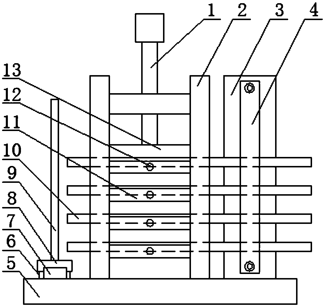
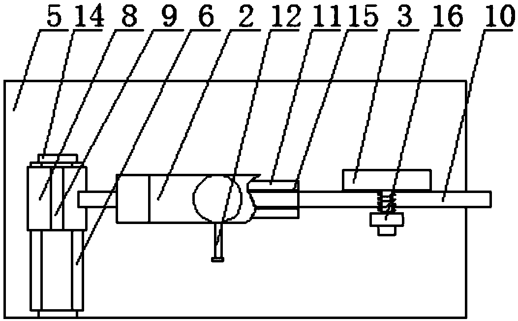
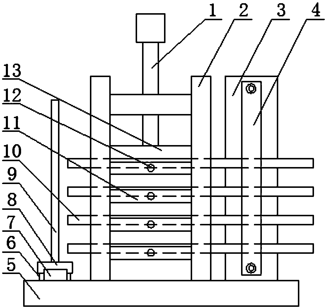
[0016] A multi-group wire cutting special device, including a base plate 5, a bracket 2, a front baffle plate 9, a vertical plate 3 and a rear pressure plate 4, a bracket is installed on the base plate, and the bracket is composed of left and right frames and an upper beam, and the side walls of the left and right frames are Both are made into a through-slot structure for passing through workpieces, and the upper parts of the left and right frames are connected by an upper crossbeam, on which a vertically arranged rotary handle 1 is installed, and the lower end of the rotary handle is connected with a horizontally arranged upper pressing block 13 , the upper pressing block is located between the left and right fr...


PUM


Abstract

The invention relates to a special device for multi-group wire-electrode cutting. The special device for the multi-group wire-electrode cutting comprises a bottom plate, a supporting frame, a front baffle, a vertical plate and a back pressing plate, wherein the supporting frame is installed on the bottom plate, and the supporting frame is composed of a left frame, a right frame and an upper crossbeam; a rotating handle vertically arranged is installed on the upper cross beam, and an upper pressing block horizontally arranged is connected to the lower end of the rotating handle; a plurality ofinstallation blocks are arranged on the bottom plate under the upper pressing block from bottom to top, and a V-shaped groove is formed in the upper surface of each installation block; and the vertical plate is installed on the bottom plate on the right side of the supporting frame, and the back pressing plate is connected to the front end face of the vertical plate through a spring pin rod. According to the special device for the multi-group wire-electrode cutting, the design is reasonable, the use is convenient and fast, and the manufacturing cost is low; the simultaneous processing of multiple workpieces can be realized by using the device, the production efficiency is greatly improved, the clamping force can be further controlled, the processing quality of the workpieces is ensured, and meanwhile, the scratches of the workpieces can be further avoided; and the special device is especially suitable for mass production.

Description

technical field [0001] The invention relates to the technical field of sewing machine needle bar processing, in particular to a multi-group thread cutting special device. Background technique [0002] The needle bar of a sewing machine is a common part, which belongs to the thin-walled part, and an opening groove needs to be made at the front end. At present, it is more convenient to use wire cutting to process it, but due to the special structure of the needle bar, there will be some problems when using wire cutting: 1. The diameter of the needle bar is small, it is not easy to clamp, and the clamping force is too small. The workpiece is easy to slide, affecting the processing. If the clamping force is too large, the needle bar will be deformed, which will increase the scrap rate and increase the raw material cost of the enterprise. 2. The existing tooling can only hold one workpiece at a time, so it can only process one workpiece at a time, resulting in low processing ef...

Claims


Application Information

Patent Timeline
Patent Type & Authority Applications(China)
IPC IPC(8): B23H11/00
CPCB23H11/003
Inventor 崔立壮
Owner TIANJIN HENGXIN PRECISION MACHINERY
Learn More