10 kV centrally installed switchgear disconnector energy storage spring dismounting and mounting tool

A technology for energy storage springs and circuit breakers, which is applied in the field of auxiliary tools for circuit breaker maintenance. It can solve the problems of different sizes of energy storage springs, the effect is not too obvious, and there is no force point, so as to achieve rapid and reliable expansion or tightening. , shorten the maintenance time of power outages, and improve the efficiency of disassembly and assembly

Pending Publication Date: 2019-07-09
JIANGSU ELECTRIC POWER CO +1
View PDF3 Cites 1 Cited by
  • Summary
  • Abstract
  • Description
  • Claims
  • Application Information

AI Technical Summary

Problems solved by technology

When the internal components of the circuit breaker (such as closing coil, energy storage motor or internal transmission connecting rod, etc.) break down and need to be repaired and replaced, the energy storage spring must be released and removed before the next step can be targeted to remove the faulty components; energy storage Even if the spring is in the energy-releasing state, it is actually a pre-stretched state, which has a lot of energy and is not easy to disassemble; when reassembling, it is necessary to stretch the energy-storing spring for a certain distance before installing the shaft pin, stretching it by hand Energy storage spring can't do it
For this reason, many researches have been done on tools and tools used for auxiliary disassembly and assembly of circuit breaker energy storage springs. For example, the Chinese patent document with the authorized announcement number CN202656147U discloses a scissors-type vacuum circuit breaker spring disassembly tool. The structure is similar to that of scissor blades. When using this tool to disassemble the energy storage spring, clamp the energy storage spring removal tool on the energy storage spring on the spring operating mechanism of the vacuum circuit breaker, and then rotate the handle to move the clamping frame downward. , so that the handles of the dismounting tool move toward each other until the blade-shaped part of the lower part of the handle is embedded in the gap of the spring, so that the energy storage spring is pushed to both ends to overcome the pre-tension force of the energy storage spring, so that the energy storage The spring is extended, the device can complete the effect of clamping the spring by turning the handle, but the effect is not too obvious when the spring is stretched to both sides, and it is more laborious to use
Another example is that the Chinese patent literature with the authorized announcement number CN207522519U discloses a vacuum circuit breaker energy storage spring disassembly and maintenance tool. Its hooked part is put into the spring, and its use has obvious limitations
Another example is that the Chinese patent literature with the authorized announcement number CN207344505U discloses a switchgear circuit breaker energy storage spring disassembler. However, the two ends of the dismantled target spring of this device must be provided with a force-bearing position that can fix its clamping plate. However, the switch The energy storage springs in cabinet circuit breakers are generally bare springs and have no stress points, so their applicability is greatly limited
[0003] As can be seen from the foregoing, the disassembly and assembly tools used in the prior art for the energy storage spring of the circuit breaker of the central cabinet are generally only designed for the disassembly and use of a certain type or type of energy storage spring. The design structure and actual layout of the cabinet circuit breaker energy storage spring are different for each manufacturer, and the size and size of the energy storage spring used are also different. Auxiliary detachment and assembly of the spring

Method used


Image

  • 10 kV centrally installed switchgear disconnector energy storage spring dismounting and mounting tool
  • 10 kV centrally installed switchgear disconnector energy storage spring dismounting and mounting tool
  • 10 kV centrally installed switchgear disconnector energy storage spring dismounting and mounting tool

Examples


Embodiment 1)

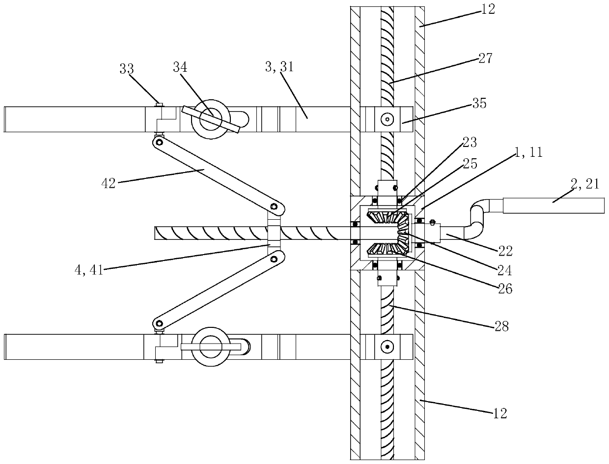
[0027] In this embodiment, when describing the orientation, use figure 1 The direction facing is the front in the description, with the back facing figure 1 The direction facing is the rear in the description, figure 1 The up and down, left and right directions in the description are still the up and down, left and right directions in the description.

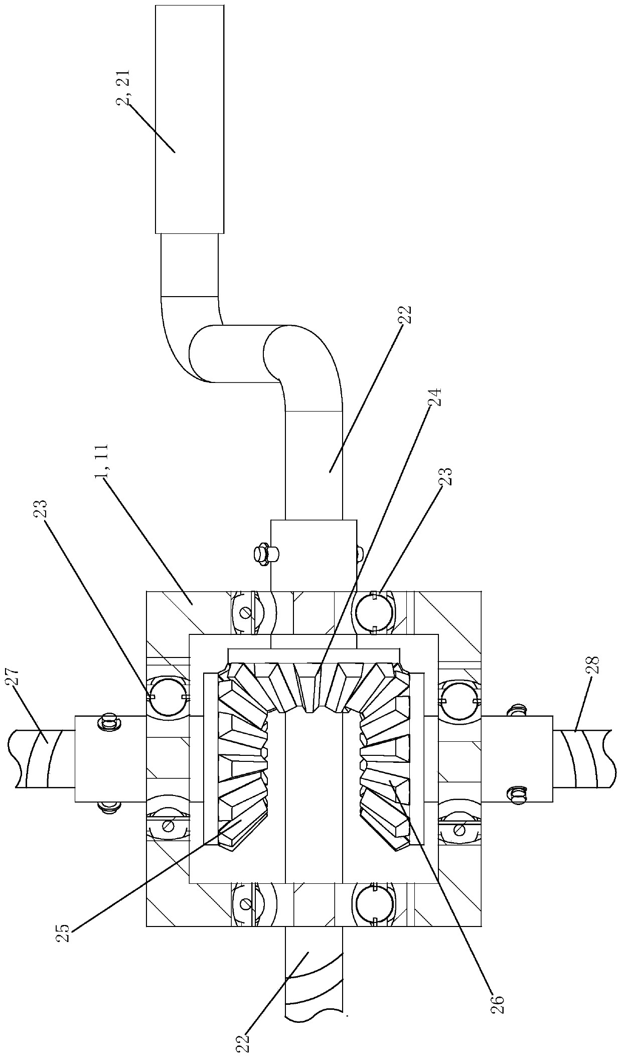
[0028] See figure 1 , The 10kV central cabinet circuit breaker energy storage spring disassembly tool of this embodiment is mainly composed of a main body 1, a drive assembly 2, a clamping and retracting assembly 3 and an auxiliary retracting assembly 4.

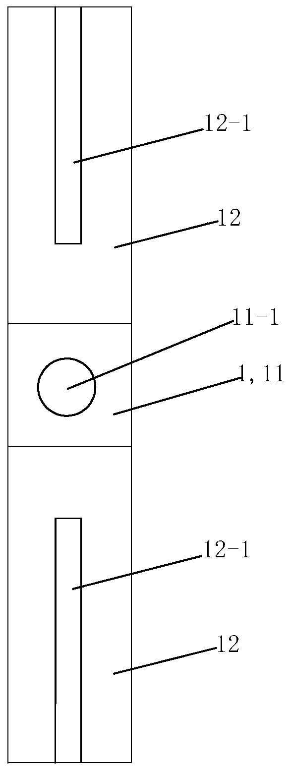
[0029] see figure 2, The body 1 is mainly composed of a gear box 11 and a mounting sleeve 12 . The gear case 11 is a hollow square box body part surrounded by each of the front, rear, upper, lower, left and right plates. The upper plate, the lower plate, the left plate and the right plate of the gear case 11 are respectively provided with A total of 4 bearing mounting h...


PUM


Abstract

The invention provides a 10 kV centrally installed switchgear disconnector energy storage spring dismounting and mounting tool. The dismounting and mounting tool comprises a body, a driving assembly arranged on the body, two clamping, stretching and retracting assemblies which are in transmission connection with the driving assembly and used for stretching or retracting an energy storage spring to be dismounted and mounted, and an auxiliary stretching and retracting assembly which is in transmission connection with the driving assembly and in pin joint with the two clamping, stretching and retracting assemblies, the driving assembly comprises a handle, a transmission rod, a bearing, a first bevel gear, a second bevel gear, a third bevel gear, a first driving screw rod and a second drivingscrew rod, the clamping, stretching and retracting assemblies comprise first clamping parts, second clamping parts, connecting pin shafts, locking screw rods and transmission nuts, and the auxiliarystretching and retracting assembly comprises a driving part and two pushing rods; and during use, the two clamping, stretching and retracting assemblies tightly hold the energy storage spring to be dismounted and mounted, then the driving assembly drives the auxiliary stretching and retracting assembly and the two clamping, stretching and contracting assemblies to do stretching or retracting actions so as to stretch or retract the energy storage springs to be dismounted and mounted respectively. The dismounting and mounting tool is suitable for dismounting and mounting the energy storage springs of various types, high in applicability, convenient to operate and capable of improving the working efficiency.

Description

technical field [0001] The invention relates to a circuit breaker maintenance auxiliary tool, in particular to a disassembly tool for an energy storage spring of a 10kV central cabinet circuit breaker. Background technique [0002] The 10kV central cabinet circuit breaker generally adopts a spring energy storage mechanism. At present, there are common models such as Senyuan VS1, Pawell WEP, General VB2, and Dongyuan VED4. There are generally two types of energy storage spring structures and installation forms used in existing common central cabinet circuit breakers. One is a bare spring, and the hook-shaped structures at both ends of the spring or the mounting holes are directly connected to the circuit breaker mechanism; the other is The two ends of the spring are installed in the ferrule, and then connected with the circuit breaker mechanism through the hook or mounting hole of the ferrule itself. When the internal components of the circuit breaker (such as closing coil, ...

Claims


Application Information

Patent Timeline
IPC IPC(8): B25B27/00B25B27/14
CPCB25B27/00B25B27/14
Inventor 张磊高佳平何蕾郝晨煜仇文艺张畅赵俊
Owner JIANGSU ELECTRIC POWER CO
Why Eureka
Try Eureka