Inclined sealing ring flow distribution mechanism, axial plunger motor and axial plunger pump

An axial piston motor and sealing ring technology, which is applied to the components of pumping devices for elastic fluids, pumps, multi-cylinder pumps, etc. The effect of wear, leakage and heat reduction

Pending Publication Date: 2019-07-09
梁德荣
View PDF0 Cites 0 Cited by
  • Summary
  • Abstract
  • Description
  • Claims
  • Application Information

AI Technical Summary

Problems solved by technology

[0004] The purpose of the present invention is to provide an inclined seal ring flow distribution mechanism to solve the technical problems of leakage and heat caused by the easy wear and friction pairs of the axial plunger movement device using the flow distribution plate, and to solve the problem of using a one-way valve flow distribution to achieve positive The technical problem of complex flow distribution structure existing in the reversal

Method used


Image

  • Inclined sealing ring flow distribution mechanism, axial plunger motor and axial plunger pump
  • Inclined sealing ring flow distribution mechanism, axial plunger motor and axial plunger pump
  • Inclined sealing ring flow distribution mechanism, axial plunger motor and axial plunger pump

Examples


Embodiment Construction

[0021] The present invention will be further described below in conjunction with the accompanying drawings and embodiments.

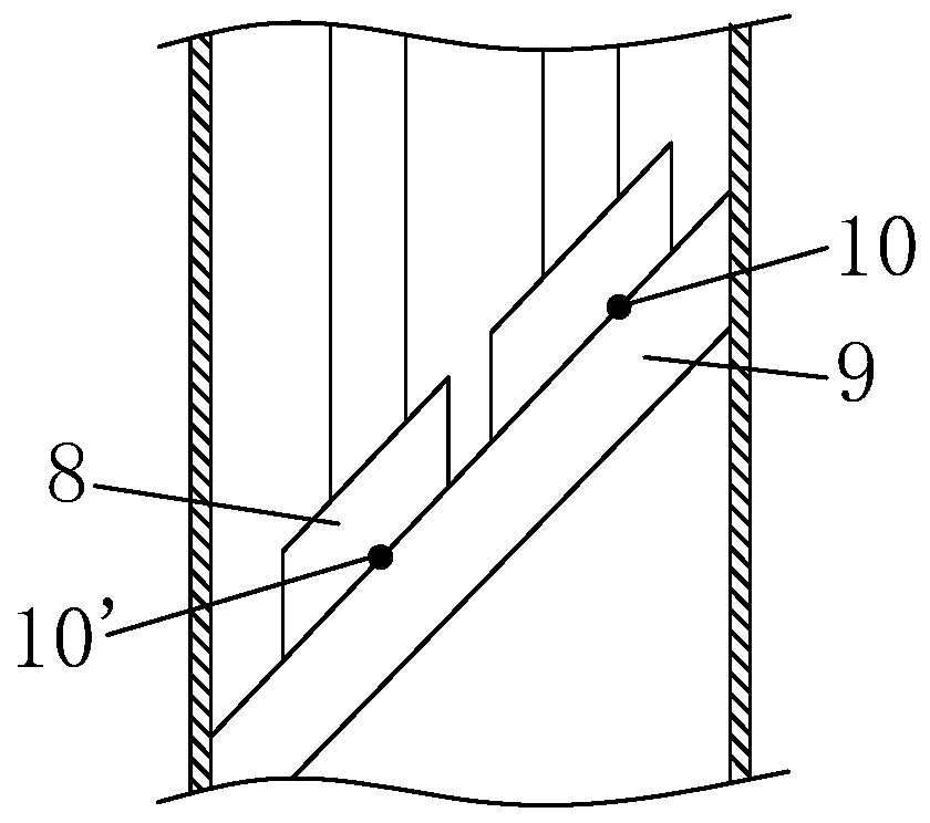
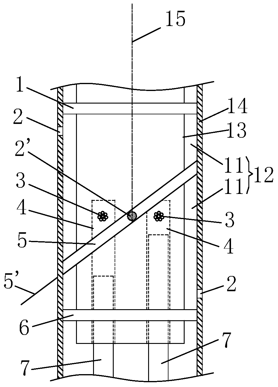
[0022] figure 1 Shown is the state after the shell is cut along the axis, figure 1 Only two plungers 7 are schematically drawn in , and actually there are more plungers. Please refer to figure 1 , the inclined seal ring flow distribution mechanism includes a first seal ring 1, a second seal ring 5 and a third seal ring 6, and the first seal ring 1, the second seal ring 5 and the third seal ring 6 are arranged at intervals The inner wall of the casing 14 of the axial piston motor forms a friction pair with the side wall of the plunger cylinder 13 of the axial piston motor, and the second sealing ring 5 connects the side wall of the piston cylinder 13 and the The annular space 12 between the casings 14 is separated to form two working fluid areas 11, and the plane 5' where the second sealing ring 5 is located is oblique to the rotation axis 15 of the p...


PUM


Abstract

The invention provides an inclined sealing ring flow distribution mechanism, an axial plunger motor and an axial plunger pump. The leakage and heating caused by abrasion of friction pairs in flow distribution of a flow distribution plate, as well as the problem that the flow distribution structure is complex when a one-way valve is used for flow distribution to achieve positive and negative rotation. A first sealing ring (1), a second sealing ring (5) and a third sealing ring (6) are arranged on an inner wall of a shell (14) of an axial plunger moving device at intervals, form a friction pairwith a side wall of a plunger cylinder (13) of the axial plunger moving device; second working medium holes (3) are respectively arranged at the position, corresponding to each plunger cavity (4), ofthe side wall of the plunger cylinder; the second working medium holes are matched with the second sealing ring, so that the plunger cavities (4) alternately communicate with two working medium areas(11) with the rotation of the plunger cylinder; and the sealing switching of working medium in and out of the plunger cavity is achieved. The axial plunger motor and the axial plunger pump comprise the flow distribution mechanism.

Description

technical field [0001] The invention relates to a flow distribution mechanism of an axial plunger movement device, in particular to a flow distribution mechanism of an inclined sealing ring. Background technique [0002] Common axial piston movement devices include axial piston motors and axial piston pumps. The existing axial plunger movement devices have the following common flow distribution methods: 1. Direct flow distribution, such as gear pump; 2. Flow distribution plate, such as vane pump and axial plunger pump; 3. Check valve flow distribution, such as single Piston pump, triple plunger pump. [0003] Due to the fact that the gears are not easy to seal, the direct distribution leads to high and low pressure flow, which makes the working efficiency of the motor or pump low. The flow distribution of the check valve is usually a fixed direction flow distribution, and the flow distribution structure to realize the forward and reverse rotation of the motor is very compl...

Claims


Application Information

Patent Timeline
Patent Type & Authority Applications(China)
IPC IPC(8): F04B1/18F04B53/00F04B27/12F04B39/00F03C1/06F03C1/36F01B3/00F01B31/00
CPCF01B3/0005F01B3/0011F01B3/0017F03C1/0613F03C1/0618F03C1/0623F04B1/141F04B1/184F04B27/1018F04B27/1036F04B27/12
Inventor 梁德荣
Owner 梁德荣
Why Eureka
Try Eureka