
Laser head lens temperature detecting system and method

A detection system and detection method technology, applied in the directions of thermometers, thermometer parts, measuring devices, etc., can solve problems such as lens damage and damage to the laser head, and achieve the effect of protection from damage and easy implementation.

Inactive Publication Date: 2019-07-09
HANS LASER TECH IND GRP CO LTD +1
View PDF4 Cites 4 Cited by
  • Summary
  • Abstract
  • Description
  • Claims
  • Application Information

AI Technical Summary

Problems solved by technology

[0002] During the working process of laser cutting and laser welding, the temperature of the lens in the laser head will increase with time. As the temperature of the lens continues to rise, it may cause damage to the lens or even damage the laser head

Method used


Image

  • Laser head lens temperature detecting system and method
  • Laser head lens temperature detecting system and method
  • Laser head lens temperature detecting system and method

Examples


Embodiment Construction

[0033] In order to facilitate the understanding of the present invention, the present invention will be described more fully below with reference to the relevant drawings. The preferred embodiments of the invention are shown in the drawings. However, the present invention can be implemented in many different forms and is not limited to the embodiments described herein. On the contrary, the purpose of providing these embodiments is to make the understanding of the disclosure of the present invention more thorough and comprehensive.

[0034] Unless otherwise defined, all technical and scientific terms used herein have the same meaning as commonly understood by those skilled in the technical field of the present invention. The terminology used in the specification of the present invention herein is only for the purpose of describing specific embodiments, and is not intended to limit the present invention.

[0035] Refer to figure 1 As shown, the present invention provides a laser he...


PUM


Abstract

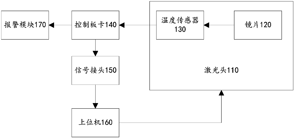
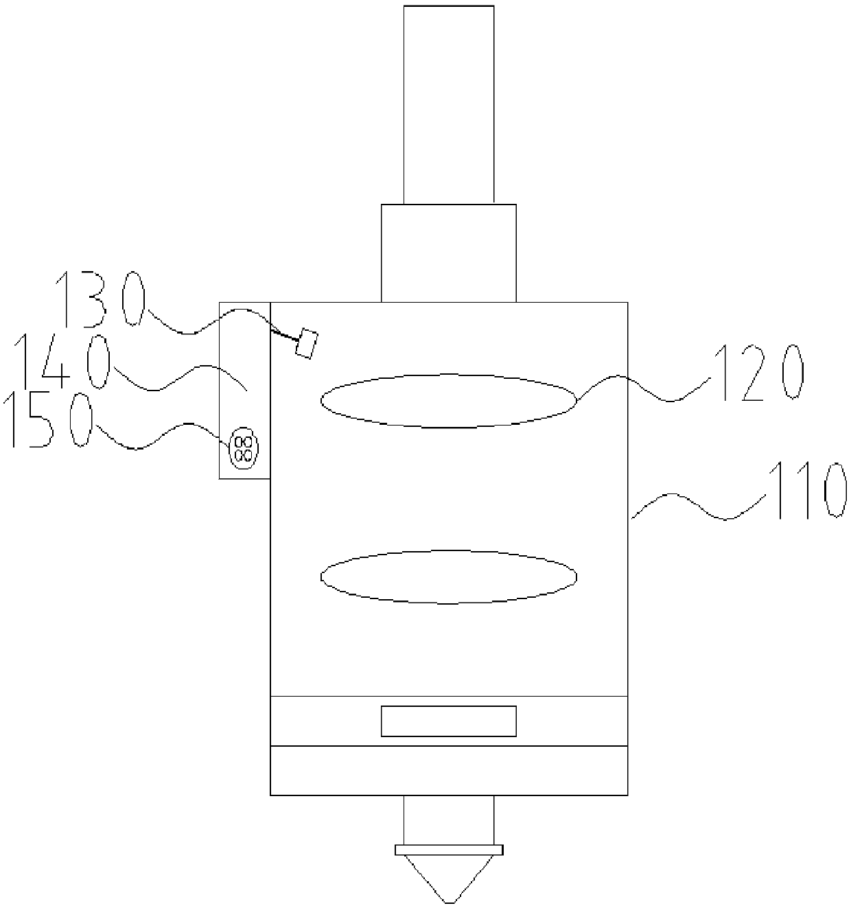
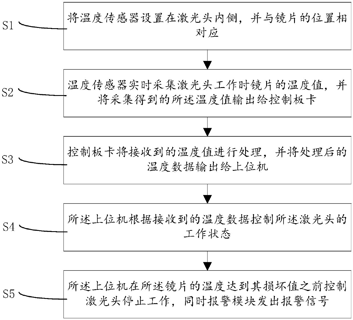
The invention relates to the technical field of laser cutting and laser welding, and discloses a laser head lens temperature detecting system and method. The detecting system comprises a laser head, alens, a temperature sensor, a control board and a host computer, wherein the temperature sensor is used for collecting a temperature value of the lens when the laser head is working, and outputting the collected temperature value to the control board; the control board processes the received temperature value and outputs the processed temperature data to the host computer; and the host computer controls the operation of the laser head according to the received temperature data, and controls the laser head to stop working before the temperature of the lens reaches its damage value. The laser head lens temperature detecting system and method can protect the lens and the cutting head from being damaged by setting the temperature sensor, and are simple, reliable and easy to implement.

Description

Technical field [0001] The present invention relates to the technical field of laser cutting and laser welding, and more specifically, to a system and method for detecting the temperature of a laser head lens. Background technique [0002] During the working process of laser cutting and laser welding, the temperature of the lens in the laser head will rise over time. As the temperature of the lens continues to rise, it may damage the lens or even damage the laser head. Summary of the invention [0003] The purpose of the present invention is to provide a laser head lens temperature detection system and method in view of the technical problems existing in the prior art. By setting a temperature sensor, the lens and the cutting head can be protected from damage, which is simple, reliable and easy to implement. [0004] In order to solve the above-mentioned problems, the technical solution adopted by the present invention is: [0005] A laser head lens temperature detection system, incl...

Claims


Application Information

Patent Timeline
Patent Type & Authority Applications(China)
IPC IPC(8): G01K1/02G01D21/02G01K1/024
CPCG01K1/024G01K1/028G01D21/02
Inventor 余锦超余锦望封雨鑫陈焱高云峰
Owner HANS LASER TECH IND GRP CO LTD
Learn More