Dynamic and fatigue performance detection device and method for steel rail assembling fastener system

A technology of fatigue performance and detection device, which is applied in the direction of measurement device, machine/structural component test, vibration test, etc., can solve the problem of inability to accurately and comprehensively predict the dynamics and fatigue mechanics of the fastener system, and achieves easy operation and low cost. low cost effect

Pending Publication Date: 2019-07-09
SHANGHAI RES INST OF MATERIALS CO LTD
View PDF0 Cites 4 Cited by
  • Summary
  • Abstract
  • Description
  • Claims
  • Application Information

AI Technical Summary

Problems solved by technology

However, the existing methods for testing the dynamic and fatigue performance of fastener systems assembled indoors only test and analyze the simple harmonic vibration response of a single low frequency (generally in the range of 3-5 Hz) and fixed amplitude, which is different from that of rails in actual lines. The vibration response is covered in the 2000Hz frequency domain, and the global dominant frequency is concentrated in the middle and low frequency bands of 20-400Hz, which is inconsistent, and the actual working bandwidth of the fastener system is affected by many factors such as driving speed and track vibration-damping structure. Therefore, traditional detection methods are used to obtain The dynamic and fatigue performance of the assembled fasteners cannot be accurately and comprehensively predicted the dynamic and fatigue mechanical behavior of the fastener system in the actual line

Method used


Image

  • Dynamic and fatigue performance detection device and method for steel rail assembling fastener system
  • Dynamic and fatigue performance detection device and method for steel rail assembling fastener system
  • Dynamic and fatigue performance detection device and method for steel rail assembling fastener system

Examples


Embodiment

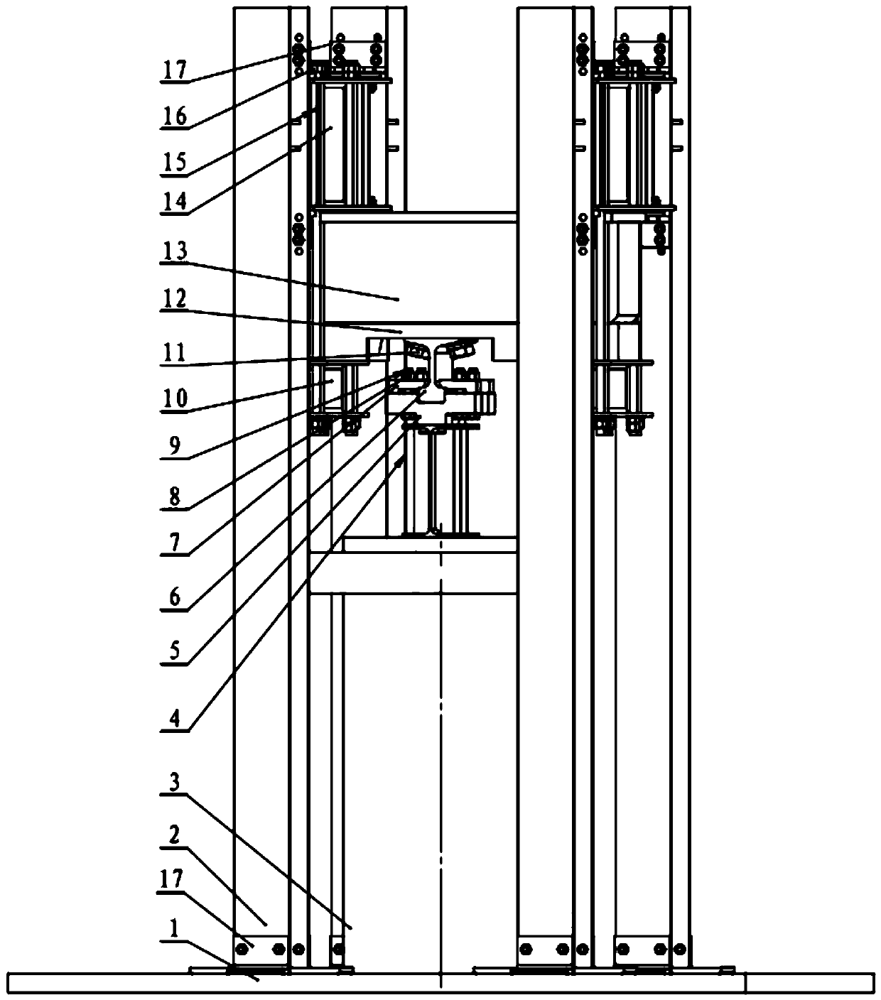
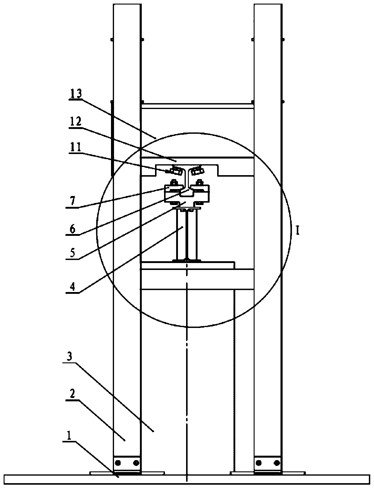
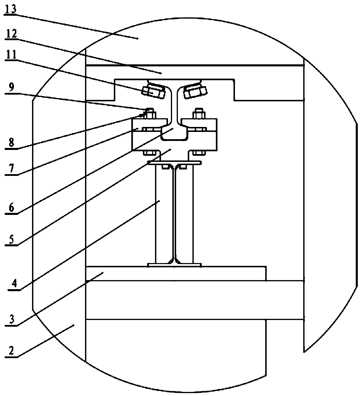
[0026] refer to Figure 1-Figure 3 , a dynamic and fatigue performance detection device of a rail assembly fastener system, used for dynamic mechanical behavior detection and fatigue performance detection of the rail assembly fastener system, the rail assembly fastener system includes rails 6, sleepers 13 and connected to The buckling element 11 between the rail 6 and the sleeper 13, the detection device includes a bottom plate 1, a vertical column 2, a vibrator 3, an actuating head 4, a transition slider 5, a tongue plate 7, an auxiliary beam 10, and a box body 12 and the upper beam 14, the vertical column 2 is fixedly connected to the base plate 1, the auxiliary beam 10 and the upper beam 14 are respectively connected to the vertical column 2, and the box 12 is located between the auxiliary beam 10 and the upper beam 14 Between, the box 12 is used to fix the sleeper 13, the vibrator 3 is fixed on the bottom plate 1, the actuating head 4 of the vibrator 3 is connected with th...


PUM


Abstract

The invention relates to a dynamic and fatigue performance detection device and method for a steel rail assembling fastener system, and is used for carrying out dynamic mechanics behavior detection and fatigue performance detection on the steel rail assembling fastener system. The detection device comprises a bottom plate, vertical stand columns, a vibration exciter, an actuation head, a transition sliding block, a tongue plate, auxiliary beams, a box body and upper cross beams, wherein the vertical stand columns are fixedly connected with the bottom plate; the auxiliary beams and the upper cross beams are independently connected with the vertical stand columns; the box body is positioned between the auxiliary beams and the upper cross beams and is used for fixing a sleeper; the vibrationexciter is fixed on the bottom plate; the actuation head of the vibration exciter is connected with the transition sliding block; the transition sliding block is used for supporting the rail head of the steel rail; and the tongue plate is used for realizing connection between the rail head of the steel rail and the transition sliding block. By use of the detection device, in the dynamic and fatigue experiment of the assembling fastener system, the influence of reality factors, including vehicle speed, axle load, rail structure, circuit line font, rail surface state and the like, can be fully considered, broadband excitation and multi-working-condition detection are realized, and in addition, the detection device is convenient in operation and low in cost.

Description

technical field [0001] The invention belongs to the technical field of railway fittings, and in particular relates to a dynamic and fatigue performance detection device and method of a rail assembly fastener system. Background technique [0002] In recent years, road transportation has increasingly caused cost effects such as environmental pollution, land occupation, energy consumption, transportation costs, and transportation safety. my country's transportation strategy has gradually changed to a model of "prioritizing the development of railways and promoting the coordinated development of railways and highways". Compared with road transportation and air transportation, rail transportation such as high-speed rail and subway has the advantages of low land and space occupancy rate, large transportation volume, fast operation speed, low environmental pollution, high comfort and high punctuality rate, so along with the urbanization process Speeding up, my country's rail transit...

Claims


Application Information

Patent Timeline
IPC IPC(8): G01M7/02
CPCG01M7/022
Inventor 刘艳朱唯丰涂田刚赵威
Owner SHANGHAI RES INST OF MATERIALS CO LTD
Why Eureka
Try Eureka