
Visual pressurized discrete particle reaction kinetics experiment system

A technology of reaction kinetics and experimental system, applied in the field of visual pressurized discrete particle reaction kinetics experimental system, can solve the problems of low heating temperature, no visual observation, slow heating rate, etc.

Active Publication Date: 2019-07-09
HUAZHONG UNIV OF SCI & TECH
View PDF8 Cites 15 Cited by
  • Summary
  • Abstract
  • Description
  • Claims
  • Application Information

AI Technical Summary

Problems solved by technology

[0003] There are many different types of pressurized experimental systems, such as pressurized thermogravimetric analyzers, pressurized burette furnaces, pressurized fixed beds and pressurized flat flame entrained flow reactors, etc., but these systems have limitations : pressurized thermogravimetry can only study particle combustion in a static state, and the heating temperature is low (generally lower than 1273K), and the heating rate is slow (3-200K / min); the pressurized dropper furnace can reach the environment of high temperature and high pressure, but Its heating rate can only reach a maximum of 10 3 -10 4 K / s; pressurized fixed bed reactants are mostly large particles or accumulated powder layers, and the temperature is generally between 723-1273K, which has a large gap with practical applications
[0004] The pressurized planar flame-carrying flow reactor uses the high-temperature flue gas generated by gas combustion to heat the particles, and its temperature can reach 1800-2000K, and the heating rate can reach 10 5 -10 6 K / s is the closest to the actual environment of particle combustion, but the existing pressurized flat flame burner equipment is basically not equipped with a visual observation system

Method used


Image

  • Visual pressurized discrete particle reaction kinetics experiment system
  • Visual pressurized discrete particle reaction kinetics experiment system
  • Visual pressurized discrete particle reaction kinetics experiment system

Examples


Embodiment Construction

[0040] In order to make the object, technical solution and advantages of the present invention clearer, the present invention will be further described in detail below in conjunction with the accompanying drawings and embodiments. It should be understood that the specific embodiments described here are only used to explain the present invention, not to limit the present invention. In addition, the technical features involved in the various embodiments of the present invention described below can be combined with each other as long as they do not constitute a conflict with each other.

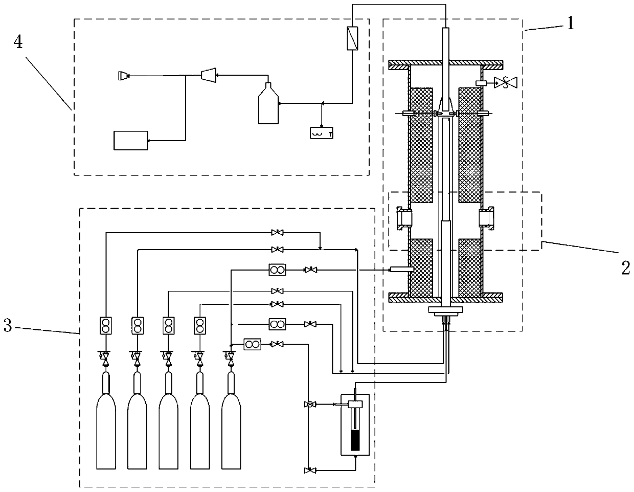
[0041] like figure 1 As shown, the present invention provides a visualization system for studying the kinetics of the pressurized reaction of discrete solid particles, which mainly consists of a pressurized reaction unit 1, an optical measurement unit 2, a pressurized air supply unit 3 and a pressurized flue gas treatment unit 4 It consists of four parts.

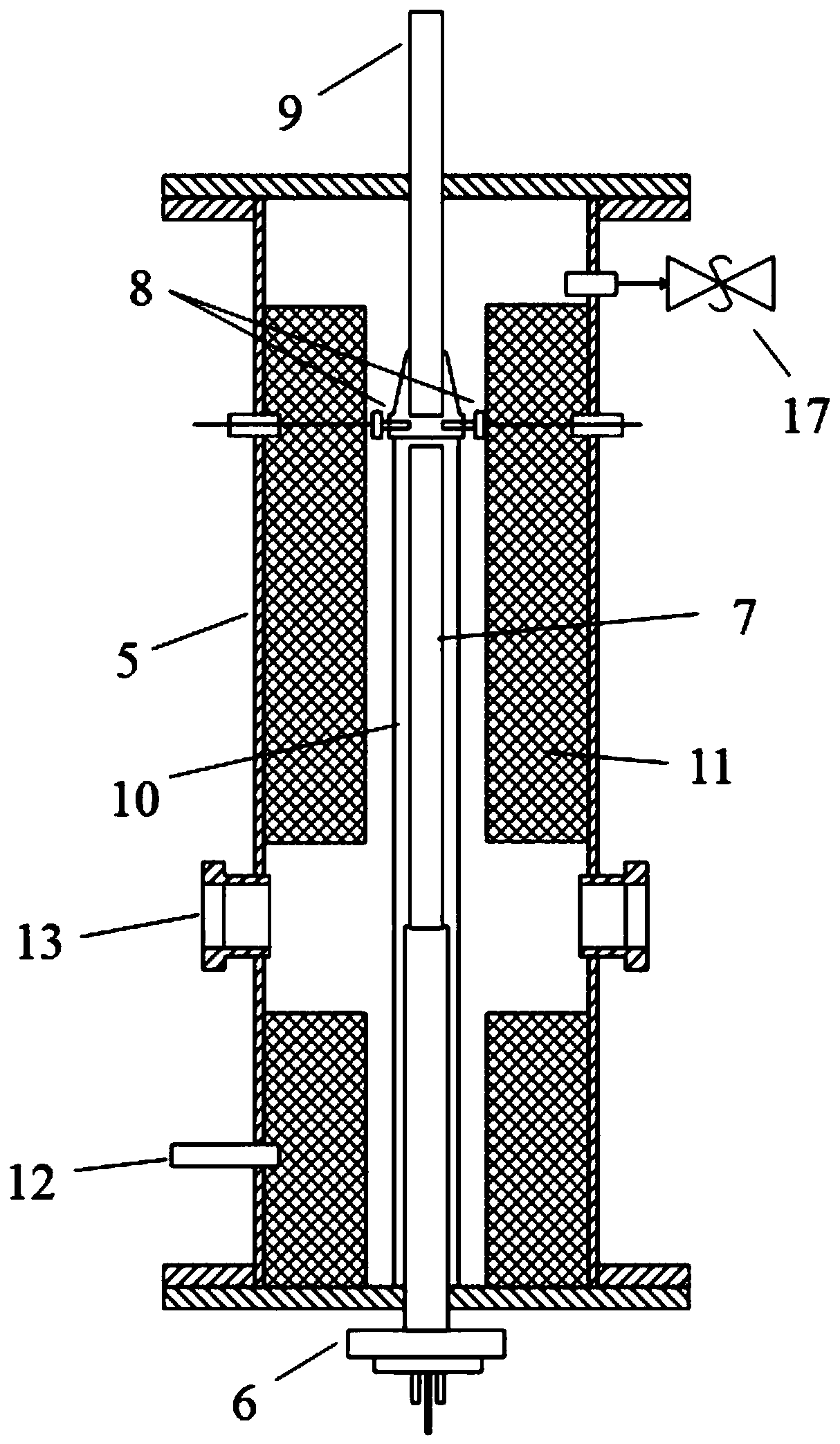
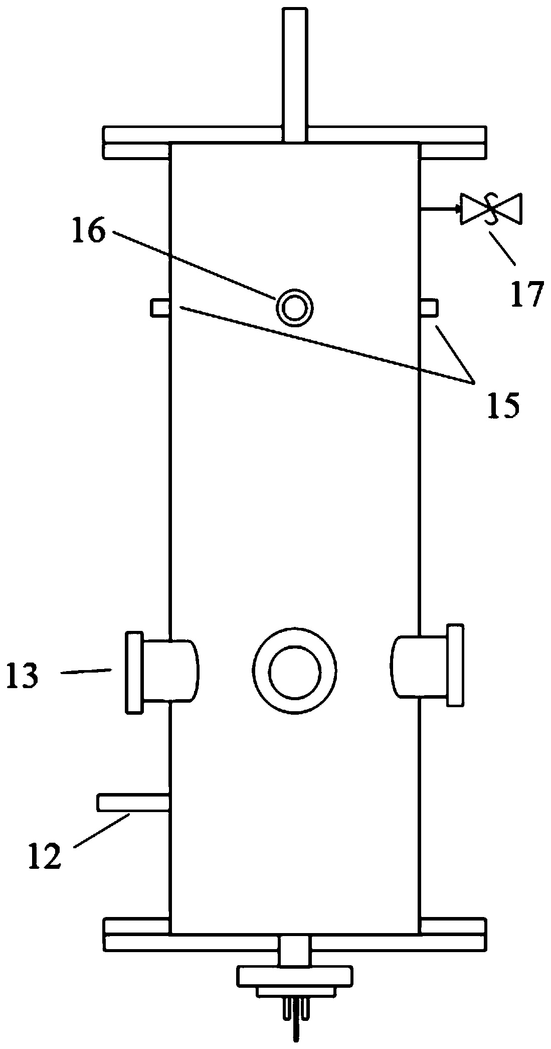
[0042] like Figure 2a is a section...


PUM


Abstract

The invention discloses a visual pressurized discrete particle reaction kinetics experiment system, and belongs to the field of study on reaction kinetics characteristics of solid fuel particles, suchas fire catching, combustion and gasification. The system is characterized in that an optical view window is formed in a pressure container; a plane flame combustor provided with double-layer squarequartz tubes is used as a heat source; and the visual monitoring on the reaction process of the solid fuel particles in high-temperature and high-pressure environment can be realized. Through the matching of continuous laser and high-speed image pick-up, the mesoscopic morphology and brightness evolution of the particles in the whole process from cold state heating to hot state fire catching luminescence to reaction exhausting can be continuously observed on line; and the characteristic parameters such as the fire catching delay time, the fire catching temperature, the particle temperature change and the particle reaction speed are favorably obtained in the subsequent process through data processing.

Description

technical field [0001] The invention belongs to the research field of reaction kinetic characteristics of solid fuel particles such as ignition, combustion and gasification, and relates to a visualized pressurized experimental system, more specifically, to a visualized pressurized discrete particle reaction kinetics experimental system. Background technique [0002] The reaction kinetic characteristics of micron and nanometer powder fuels such as ignition, combustion and gasification have important reference significance for the design of combustion devices. In practical applications, powder reactions are often in extreme high-temperature and high-pressure environments, which are difficult for most laboratory equipment to achieve. Therefore, there is an urgent need for an experimental system that can simulate the ignition and combustion of fuel particles in an extreme high temperature and high pressure environment, and can accurately and effectively monitor the process. [...

Claims


Application Information

Patent Timeline
IPC IPC(8): G01N21/84G01N25/12G01N25/22G01N25/28G01N25/38G01N33/00
CPCG01N21/84G01N25/22G01N25/28G01N25/38G01N25/385G01N25/12G01N33/0004G01N33/0036G01N33/0037G01N33/0042G01N33/0091
Inventor 栗晶陈前云王昱升张泰柳朝晖
Owner HUAZHONG UNIV OF SCI & TECH
Learn More