Shunt integrated device for a multi-stack fuel cell engine system

An engine system and fuel cell technology, applied in fuel cells, electrochemical generators, circuits, etc., can solve the problems of difficult reduction in the size of the engine system, the large space occupied by pipelines, and the reduction of operating space, etc., to achieve simple, compact, Compact structure, convenient maintenance and installation

Pending Publication Date: 2019-07-09
上海楞次新能源汽车科技有限公司
View PDF2 Cites 8 Cited by
  • Summary
  • Abstract
  • Description
  • Claims
  • Application Information

AI Technical Summary

Problems solved by technology

Firstly, the complicated and long pipes take up a lot of space, which makes it difficult to reduce the volume of the engine system; secondly, the mounting bracket of the electric stack should be fixed at other parts, so that the parts under the electric stack are densely packed, resulting in the tightening of screws, clamps, etc. The operating space of the firmware is reduced; finally, all components are installed and connected in series in the pipeline, which has low integration and takes up a lot of space

Method used


Image

  • Shunt integrated device for a multi-stack fuel cell engine system
  • Shunt integrated device for a multi-stack fuel cell engine system
  • Shunt integrated device for a multi-stack fuel cell engine system

Examples


Embodiment Construction

[0041] The present invention will be further described below in conjunction with the following embodiments. It should be understood that the following examples are only used to further illustrate the present invention, and cannot be interpreted as limiting the protection scope of the present invention. Non-essential improvements and adjustments all belong to the protection scope of the present invention. The specific process parameters and the like in the following examples are only examples of suitable ranges, that is, those skilled in the art can make a selection within a suitable range through the description herein, and are not limited to the specific values ​​exemplified below. In each figure, the same or corresponding reference numerals denote the same components, and repeated explanations will be omitted.

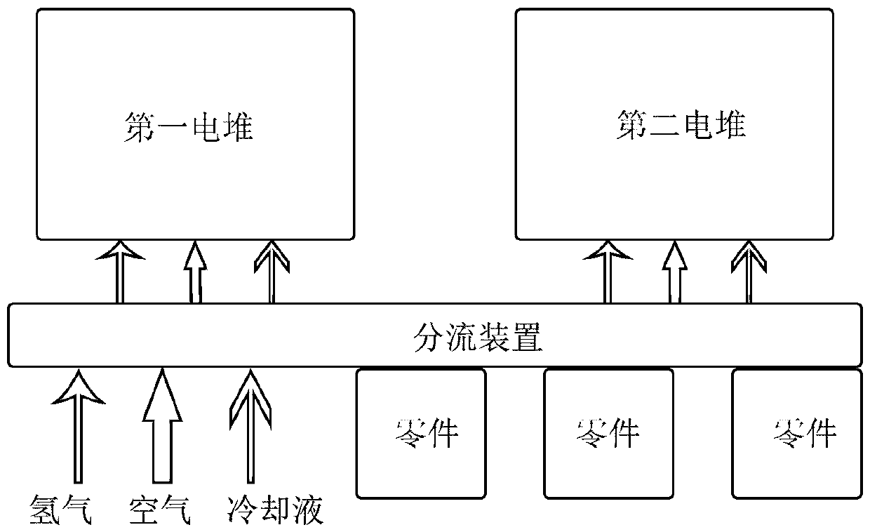
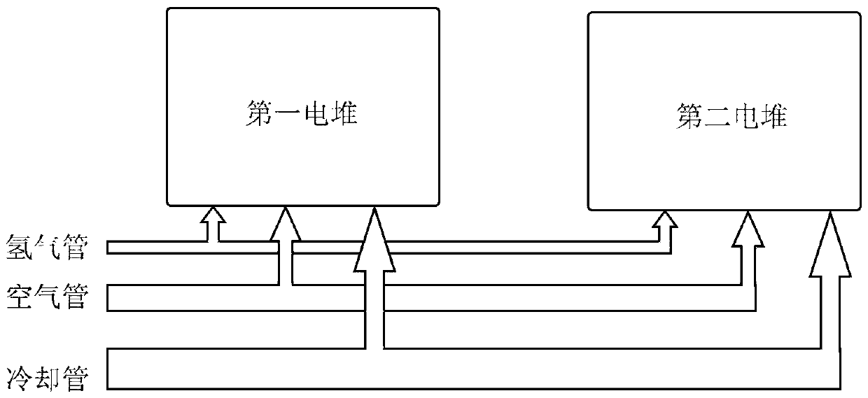
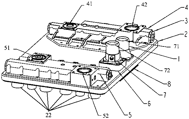
[0042] Disclosed here is a flow distribution integration device for a multi-stack fuel cell engine system, including: a flow distribution plate 2 used for system loa...


PUM


Abstract

The invention provides a shunt integrated device for a multi-stack fuel cell engine system. The shunt integrated device comprises a shunt plate used for bearing the weight of the system and internallyprovided with multiple flow channel grooves for guiding the directional flow of fluid, a cover plate forming a cooling flow channel together with the flow channel grooves of the shunt plate, and a hydrogen-input air-output integrated plate and a hydrogen-output air-input integrated plate which respectively form an air flow channel and a hydrogen flow channel together with the flow channel groovesof the shunt plate. Multiple stack connection ports, a coolant outlet and a coolant inlet are formed in the shunt plate. A hydrogen inlet and an air outlet as flow channel holes are formed in the other side, opposite to the cover plate, of the hydrogen-input air-output integrated plate. A hydrogen outlet and an air inlet as flow channel holes are formed in the other side, opposite to the cover plate, of the hydrogen-output air-input integrated plate. According to the invention, the beneficial effects of compact structure, flexible connection mode and good mechanical performance can be achieved through the shunt device.

Description

technical field [0001] The invention relates to a split flow integration device for a multi-stack fuel cell engine system. Background technique [0002] Currently, in commonly used fuel cell engine systems, such as image 3 As shown in the figure, the connection between the air circuit, hydrogen circuit and cooling circuit as the interface of the multi-cell stack flow channel and other parts of the engine is usually through pipes of different shapes (such as image 3 The air pipes, hydrogen pipes, and cooling pipes connected to the first electric stack and the second electric stack, etc. are shown). The common pipes include stainless steel pipes, silicone pipes, etc. [0003] Although the design of this connection method is simple, there are many problems that follow. Firstly, the complicated and long pipes take up a lot of space, which makes it difficult to reduce the volume of the engine system; secondly, the mounting bracket of the electric stack should be fixed at other ...

Claims


Application Information

Patent Timeline
Patent Type & Authority Applications(China)
IPC IPC(8): H01M8/0258H01M8/2483
CPCH01M8/2483H01M8/0258Y02E60/50
Inventor 马天才刘通朱东
Owner 上海楞次新能源汽车科技有限公司
Why Eureka
Try Eureka