Eureka AIR delivers breakthrough ideas for toughest innovation challenges, trusted by R&D personnel around the world.

Large-scale MIMO antenna

A large-scale antenna technology, applied in antennas, antenna arrays, antenna grounding devices, etc., can solve the problems of high integration of power distribution boards and calibration boards, affecting material costs, high material costs of power distribution boards and calibration boards, and achieve Guaranteed phase consistency and linearity, improved consistency and reliability, and optimized size design effects

Pending Publication Date: 2019-07-09
ZHONGTIAN BROADBAND TECH +1
View PDF11 Cites 4 Cited by
  • Summary
  • Abstract
  • Description
  • Claims
  • Application Information

AI Technical Summary

Problems solved by technology

[0002] The existing antennas mainly have the problems of high integration and high material cost, mainly related to: 1. The power distribution board and the calibration board are highly integrated, which is inconvenient for manufacturing and quality control; the power distribution boards of the prior art adopt full-page design , that is, all radiating units are welded on the same power splitter board, but it is inconvenient to carry out automatic welding design, and it is not convenient to carry out inspection, maintenance or replacement separately, and there is a risk of scrapping the entire antenna due to the failure of a certain module
Second, the material cost of the power distribution board and the calibration board is high; the existing technology integrates the power distribution board and the calibration board, the processing is complicated, and because of the intricate wiring inside, it is difficult to achieve the optimal size of the PCB board, which affects the material cost

Method used


Image

  • Large-scale MIMO antenna
  • Large-scale MIMO antenna
  • Large-scale MIMO antenna

Examples


Embodiment Construction

[0030] Embodiments of the present invention are described in detail below, examples of which are shown in the drawings, wherein the same or similar reference numerals designate the same or similar elements or elements having the same or similar functions throughout. The embodiments described below by referring to the figures are exemplary and are intended to explain the present invention and should not be construed as limiting the present invention.

[0031] In describing the present invention, it should be understood that the terms "length", "width", "upper", "lower", "front", "rear", "left", "right", "vertical", The orientation or positional relationship indicated by "horizontal", "top", "bottom", "inner", "outer", etc. are based on the orientation or positional relationship shown in the drawings, and are only for the convenience of describing the present invention and simplifying the description, rather than Nothing indicating or implying that a referenced device or element...


PUM


Abstract

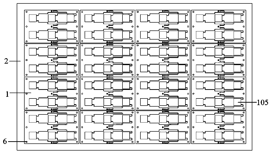
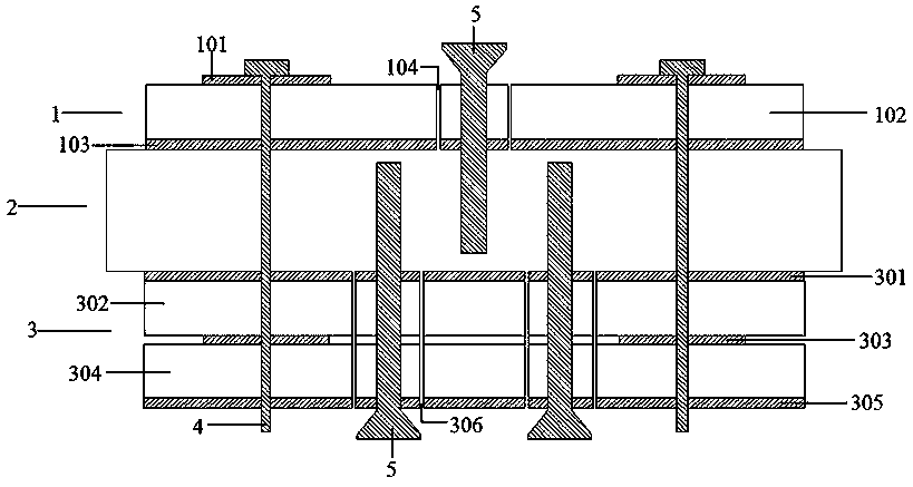
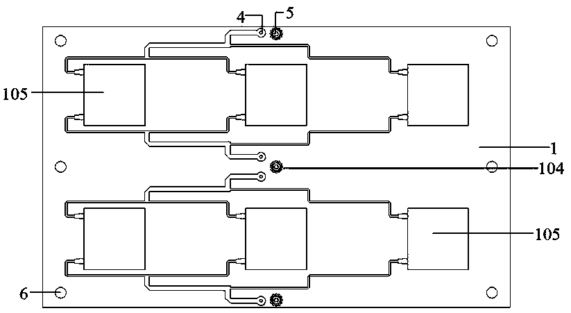
The invention belongs to the technical field of communication, and relates to a large-scale MIMO antenna comprising a reflection plate, a calibration network arranged on one side of the reflection plate and N*M antenna subarrays arranged on the side of the reflection plate away from the calibration network, wherein N is a positive integer greater than or equal to 1 and M is a positive integer greater than or equal to 2. The antenna subarrays comprises a power dividing plate and a radiation unit arranged on the power dividing plate. The power dividing plate has a microstrip line structure. Thecalibration network has a microstrip line structure or a strip-line structure. The thickness of the reflection plate is 1.5mm-3mm. The antenna subarrays are connected with the calibration network through a probe. The antenna subarrays and the calibration network are respectively connected with the reflection plate through metal screws, and at least one metal screw is arranged around the probe. Theantenna subarrays, the calibration network and the reflection plate are modularized so that detection, maintenance or replacement of a single module can be facilitated; besides, at least one metal screw is directly grounded around the feeding probe so that the antenna signal transmission is good.

Description

technical field [0001] The invention belongs to the technical field of communication, and relates to a massive MIMO antenna. Background technique [0002] The existing antennas mainly have the problems of high integration and high material cost, mainly related to: 1. The power distribution board and the calibration board are highly integrated, which is inconvenient for manufacturing and quality control; the power distribution boards of the prior art adopt full-page design , that is, all radiating units are welded on the same power distribution board, but it is inconvenient to carry out automatic welding design, and it is not convenient to carry out inspection, maintenance or replacement separately, and there is a risk of scrapping the entire antenna due to the failure of a certain module. Second, the material cost of the power distribution board and the calibration board is high; the existing technology integrates the power distribution board and the calibration board, the p...

Claims


Application Information

Patent Timeline
Patent Type & Authority Applications(China)
IPC IPC(8): H01Q1/36H01Q1/38H01Q1/48H01Q1/50H01Q21/00
CPCH01Q1/50H01Q21/00H01Q1/38H01Q1/36H01Q1/48Y02D30/70
Inventor 周献庭葛磊黄新文
Owner ZHONGTIAN BROADBAND TECH
Why Eureka
Eureka Blog
Learn More