Check patentability & draft patents in minutes with Patsnap Eureka AI!

PFC circuit

A circuit and branch technology, applied in the field of PFC circuits based on coupled inductors, can solve problems such as difficulty in meeting high power requirements, achieve good current sharing effect, good safety and reliability, and increase system costs.

Active Publication Date: 2019-07-09
DELTA ELECTRONICS SHANGHAI CO LTD
View PDF8 Cites 1 Cited by
  • Summary
  • Abstract
  • Description
  • Claims
  • Application Information

AI Technical Summary

Problems solved by technology

like figure 1 As shown, the PFC circuit includes two conversion branches Z1, and each conversion branch Z1 includes a switch unit A1, but in actual use, due to the limitation of the power of the switch unit, it is difficult for a single switch unit to meet the high power requirements

Method used


Image

  • PFC circuit
  • PFC circuit
  • PFC circuit

Examples


Embodiment Construction

[0060] The present invention is described in further detail below in conjunction with accompanying drawing and specific embodiment: present embodiment is carried out under the premise of technical solution of the present invention, has provided embodiment and operation process, but protection scope of the present invention is not limited to following Example.

[0061] It should be noted that the number of switch units and coupled inductors described below is only one embodiment of the present invention, and those skilled in the art can fully adjust the number of switch units and coupled inductors according to the use requirements under the concept of the present invention. adjustment, so the present invention does not limit the number of switch units and coupled inductors.

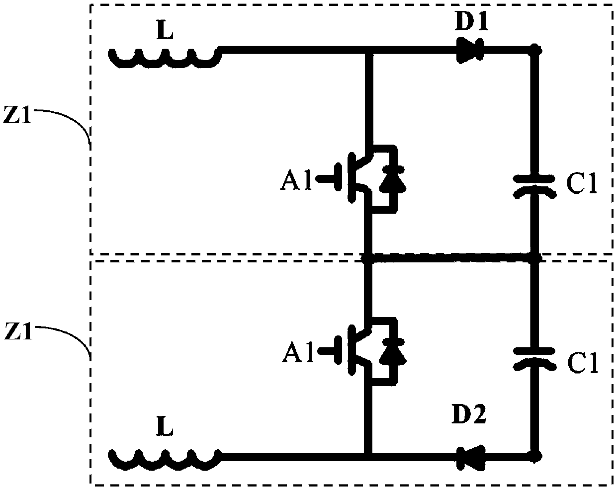
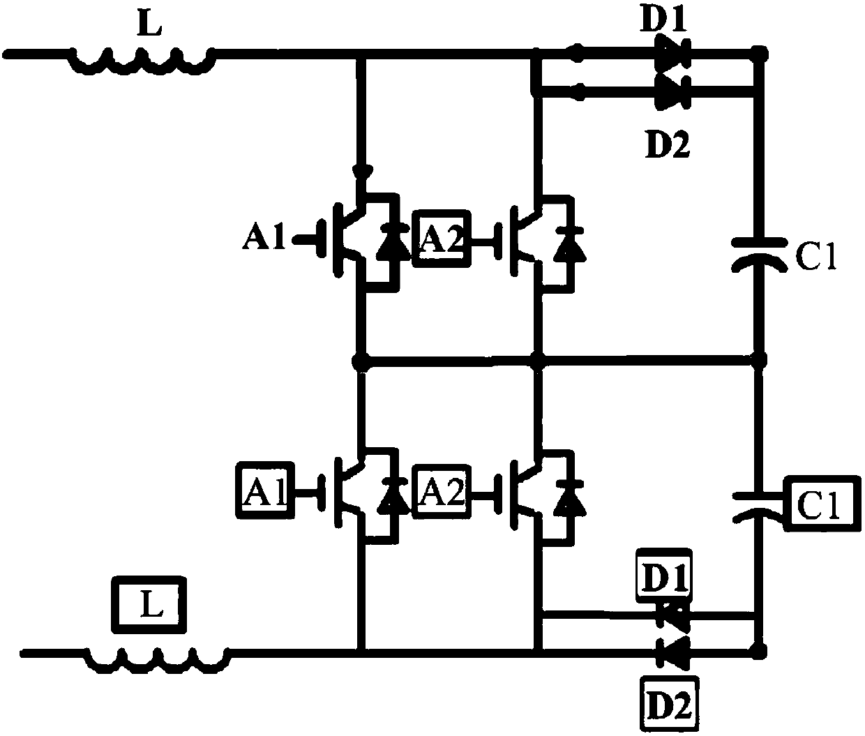
[0062] In order to be suitable for high-power applications, each switching branch in the PFC circuit includes two or more switching units connected in parallel. In order to reduce system cost, these parall...


PUM


Abstract

The invention discloses a PFC circuit, comprising two conversion branches which are electrically connected, wherein the each conversion branch comprises an input inductor, n switching units and n-1 coupling inductors, one end of the input inductor is connected with an input power supply; the n switching units are connected in parallel, and the n is a positive integer greater than or equal to 2; the each coupling inductor comprises two windings, and the two windings form reverse coupling; at least one winding is connected in series between the each switching unit and the other end of the inputinductor, when the n switching units are conducted, a current flowing through the n switching units is equalized through the n-1 coupling inductors.

Description

technical field [0001] The present invention relates to a PFC circuit, in particular to a PFC circuit based on coupled inductance. Background technique [0002] With the continuous improvement of the power level of power electronic equipment, it is difficult for a single switch tube or switch module to meet the power requirements, so it is often necessary to use multiple switch tubes in parallel in practical applications, but at the same time it brings new problems, that is, in practical applications Due to the difference between the switch tube and the circuit, there is an uneven current phenomenon between the switch tubes, which further reduces the reliability and safety of the power electronic equipment. [0003] The commonly used method to solve the uneven current between parallel switching tubes is to achieve better current sharing between the switching tubes by designing symmetrical drive and main circuits. However, due to the high switching speed and the difficulty i...

Claims


Application Information

Patent Timeline
IPC IPC(8): H02M1/42
CPCH02M1/4208Y02B70/10
Inventor 田龙祥周志健廖仁诠
Owner DELTA ELECTRONICS SHANGHAI CO LTD
Features
  • R&D
  • Intellectual Property
  • Life Sciences
  • Materials
  • Tech Scout
  • Unparalleled Data Quality
  • Higher Quality Content
  • 60% Fewer Hallucinations
Learn More