Antenna system and network equipment

An antenna system and lens antenna technology, applied in the field of communication, can solve the problems of high electromagnetic wave transmission loss, large multi-beam antenna size, and difficult implementation, and achieve the effects of suppressing communication interference, saving time-frequency resources, and improving communication efficiency

Active Publication Date: 2019-07-09
HUAWEI TECH CO LTD
View PDF4 Cites 3 Cited by
  • Summary
  • Abstract
  • Description
  • Claims
  • Application Information

AI Technical Summary

Problems solved by technology

[0003] The millimeter wave frequency band faces several outstanding problems: 1. How to solve the problem of high electromagnetic wave transmission loss, for example: the propagation loss of 60GHz in the air is about 22dB higher than that of 5GHz
The primary wall reflection loss is about 10dB, and the secondary wall reflection loss is about 16dB
2. Millimeter wave systems generally use narrow beam coverage, and the coverage of a single beam is limited. Therefore, it is necessary to provide coverage in multiple directions
However, for multi-directional coverage requirements, the industry mainly adopts simple phased array antennas and physical placement of multiple antennas. These technologies are difficult to implement and have low performance. For example, phased arrays are mainly single-beam, and multi-beam gain Such indicators are poor; physical placement / stacking of multi-beam antennas is bulky and difficult for engineering applications
Therefore, the existing multi-beam antenna technology is difficult to meet the simultaneous multi-beam and multi-user coverage requirements of future mobile communication and fixed access communication.

Method used


Image

  • Antenna system and network equipment
  • Antenna system and network equipment
  • Antenna system and network equipment

Examples


Embodiment Construction

[0045] Embodiments of the present invention will be described below with reference to the drawings in the embodiments of the present invention.

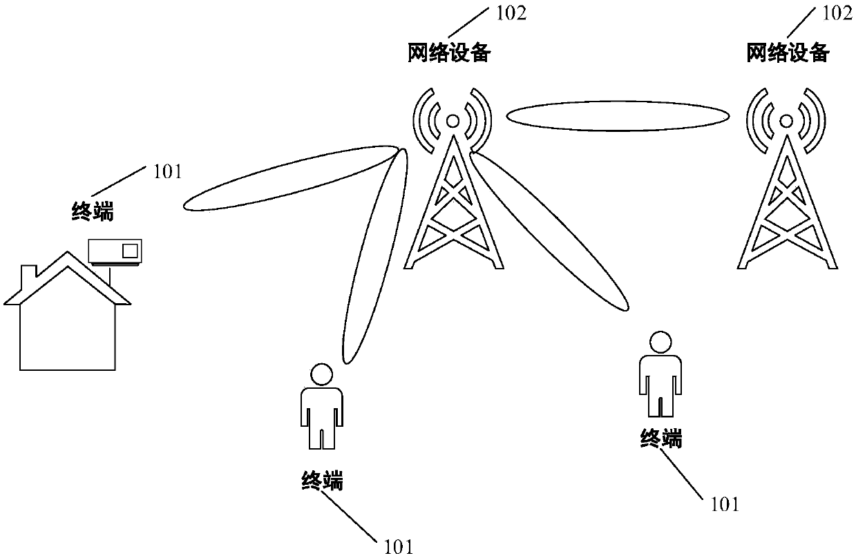
[0046] See figure 1 , figure 1 It is a schematic structural diagram of a communication system 10 provided by an embodiment of the present invention. The communication system includes a terminal 101 and a network device 102. The communication system may also include other devices; optionally, the devices in the communication system 10 may use wireless For example, the wireless communication technology can be the second-generation mobile communication technology (the 2nd-generation, 2G), the third-generation mobile communication technology (the 3rd-generation, 3G), LTE, the fourth-generation mobile communication technology technology (the 4th generation mobile communication, 4G), the fifth generation mobile communication technology (the 5th-generation, 5G), or wireless fidelity (wireless-fidelity, WI-FI) technology, or other existing ...


PUM


Abstract

The embodiment of the invention provides an antenna system and network equipment. The antenna system comprises a baseband processing unit, a control unit, at least one radio frequency channel, an array selection switch, at least two sub-arrays and a lens antenna, and is characterized in that the baseband processing unit is used for converting a bit stream signal needing to be sent to user equipment (UE) into an analog signal and sending information of a cell to which the UE belongs to the control unit; the control unit is used for determining a first channel for processing the analog signal from the at least one radio frequency channel and sending information of the first channel to the baseband processing unit; the baseband processing unit is also used for receiving the information of thefirst channel and sending the analog signal to the first channel for processing according to the information of the first channel; and the first sub-array is used for focusing and transmitting the signal received from the first channel through the lens antenna. By adopting the embodiment of the invention, multi-beam high-gain directional coverage can be realized.

Description

technical field [0001] The present invention relates to the field of communication technology, in particular to an antenna system and network equipment. Background technique [0002] With the rapid development of mobile services, the demand for spectrum in cellular mobile communication systems has increased dramatically. However, the available spectrum resources of Sub6GHz low frequency are relatively scarce, and the evolution of the cellular mobile communication system to the millimeter wave (mmWave) frequency band has become an inevitable trend. [0003] The millimeter wave frequency band faces several outstanding problems: 1. How to solve the problem of high electromagnetic wave transmission loss, for example: the propagation loss of 60GHz in the air is about 22dB higher than that of 5GHz. The 60GHz wavelength is only 5 millimeters (mm), so there is basically no diffraction and diffraction in space transmission, the penetration loss is 30dB-40dB, and it is basically impo...

Claims


Application Information

Patent Timeline
Patent Type & Authority Applications(China)
IPC IPC(8): H04B7/06H01Q3/24H01Q21/29H01Q21/00
CPCH01Q3/247H01Q21/00H01Q21/29H04B7/0408H04B7/0617
Inventor 孙德福蒋成钢罗龙王学寰
Owner HUAWEI TECH CO LTD
Why Eureka
Try Eureka