Surface acoustic wave device

A technology of surface acoustic wave and surface propagation, applied in the direction of impedance network, electrical components, piezoelectric/electrostrictive/magnetostrictive devices, etc., can solve problems such as insufficient to solve challenges

Pending Publication Date: 2019-07-09
HUAWEI TECH CO LTD
View PDF14 Cites 3 Cited by
  • Summary
  • Abstract
  • Description
  • Claims
  • Application Information

AI Technical Summary

Problems solved by technology

[0008] While these structures have been explored, they are insufficient to address specific challenges as described in this paper

Method used


Image

  • Surface acoustic wave device
  • Surface acoustic wave device
  • Surface acoustic wave device

Examples


Embodiment Construction

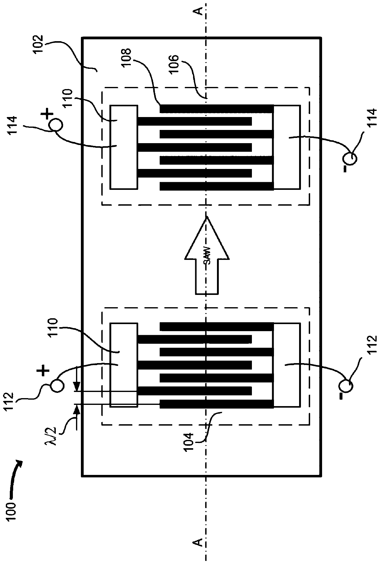
[0049] Figure 1A and Figure 1B An example of a physical implementation of a surface acoustic wave (SAW) device 100 , such as a transversal filter or a resonator filter, respectively, is shown in . Although the following description is described with reference to a particular SAW device 100, the techniques described herein may be equally applicable to other types of SAW filters and / or resonators. For example, any SAW transducer, interdigital transducer (IDT), interdigitated interdigital transducer (IIDT), ladder filter or may include the Other types of multilayer structures.

[0050] see Figure 1A In the specific example shown in , a SAW device 100 (in this exemplary embodiment a basic filter) may include a multilayer body 102 (discussed further below) having an input transformer 104 and an output transformer Converter 106, input converter 104 and output converter 106 are each represented by their corresponding dashed boxes. An input transducer 104 and an output transduce...


PUM


Abstract

The embodiments herein relate to surface acoustic wave (SAW) devices, such as filters and duplexers. The SAW device may have a high acoustic velocity layer and a piezoelectric layer coupled to the high acoustic velocity layer. At least one transducer is coupled at least to the piezoelectric layer, where the transducer propagates a surface acoustic wave having an operating wavelength along a surface of the piezoelectric layer. A metallic layer may be coupled to the surface of the piezoelectric layer and electrically isolated from the transducer.

Description

[0001] cross reference [0002] This application claims priority to US Patent Application No. 15 / 361,054, entitled "Surface Acoustic Wave Device," filed November 24, 2016, the entire contents of which are incorporated herein by reference. technical field [0003] Embodiments disclosed herein relate to surface acoustic wave (SAW) devices. In particular, embodiments relate to SAW filters, resonators and / or duplexers with improved electromechanical coupling and surface wave velocity. Background technique [0004] In communication systems (terminal and base station infrastructure), Surface Acoustic Wave (SAW) filters and resonators are widely used. For new standards such as E-UTRA used in 5G-TG4-CA, there is a growing demand for higher operating frequency, lower insertion loss, higher transmit power and / or wider channel bandwidth. It is expected that new piezoelectric materials or structures can meet the increasing demands for higher frequencies and wider channel bandwidths. ...

Claims


Application Information

Patent Timeline
Patent Type & Authority Applications(China)
IPC IPC(8): H03H9/64
CPCH03H3/08H03H9/02574H03H9/02582H10N30/10513
Inventor 陈卓辉
Owner HUAWEI TECH CO LTD
Why Eureka
Try Eureka