
Control method for improving wear resistance of gearbox

A control method and gearbox technology, which is applied in the field of gearboxes, can solve the problems of small variation range of engine torque, reduce the service life of gearboxes, and mixed ferromagnetic debris, so as to improve the effect of iron filings removal, reduce wear, and reduce The effect of loss

Active Publication Date: 2019-07-12
浙江瑞格智能科技股份有限公司
View PDF12 Cites 0 Cited by
  • Summary
  • Abstract
  • Description
  • Claims
  • Application Information

AI Technical Summary

Problems solved by technology

[0002] At present, the torque variation range of the automobile engine is small, and it cannot cope with the complicated road conditions encountered by the automobile in actual driving, so it is imperative to increase the traction force and driving speed of the automobile, and the generation of the gearbox is a good solution To solve the problems mentioned above, the gearbox adapts to the frequently changing driving conditions by changing the transmission ratio and expanding the range of driving wheel torque and speed. At the same time, the engine works under favorable conditions, with high power and low fuel consumption. In addition, the gearbox can make the car run backwards under the condition that the engine rotation direction remains unchanged. The neutral gear can interrupt the power transmission, which is convenient for the transmission to shift gears or perform power output. In actual use, the internal parts of the gearbox will be affected differently. The degree of wear and tear, the ferromagnetic debris generated by the wear is mixed in the gearbox oil and causes varying degrees of damage to the internal components of the gearbox, forming a vicious circle and greatly reducing the service life of the gearbox

Method used


Image

  • Control method for improving wear resistance of gearbox
  • Control method for improving wear resistance of gearbox
  • Control method for improving wear resistance of gearbox

Examples


Embodiment Construction

[0072] The control method for improving the wear resistance of the gearbox comprises the following steps:

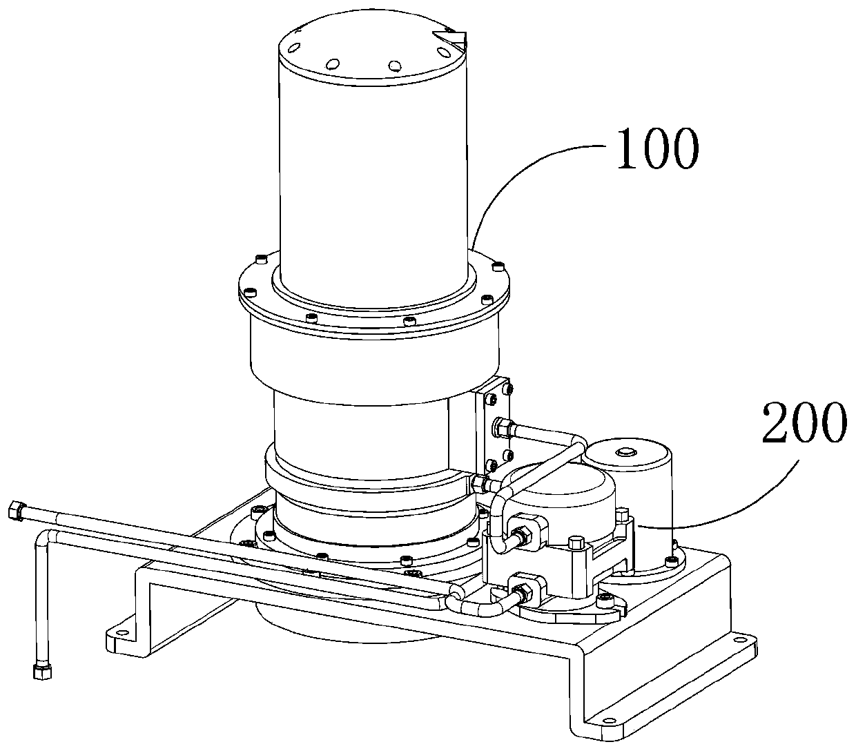
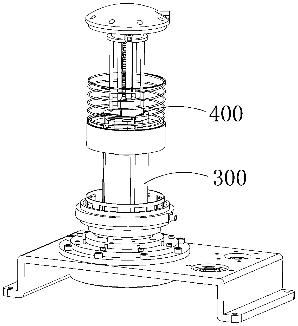
[0073] S1: the transition device 200 installed on the base sucks the gearbox oil into the installation housing 100;

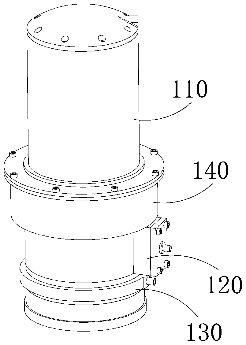
[0074] The installation housing 100 includes a main housing 110. The main housing 110 is a circular cylindrical structure with two ends open and arranged vertically. The outer circular surface of the main housing 110 is sequentially provided with chip outlets from top to bottom. Port 113, oil inlet 111, and oil outlet 112. The outside of the main housing 100 is also provided with a debris storage shell 140, an oil inlet shell 120, and an oil outlet shell 130 in sequence from top to bottom. The oil inlet nozzle 121 connected to the oil port 111 is connected to the oil outlet shell 130. The oil outlet nozzle connected to the oil outlet 112 is arranged on the oil outlet shell 130. The connection between the oil inlet nozzle 121 and the oil inlet 111 is also ...


PUM


Abstract

The invention discloses a control method for improving the wear resistance of a gearbox. The method comprises the steps that a motor operates and drives an oil pump to operate, the oil pump operates and sucks the gearbox oil through an oil guiding pipe network, and the gearbox oil is atomized by an atomizing nozzle and then is sprayed into a main casing by an oil inlet; a separating mechanism magnetically adsorbs ferromagnetic debris in the gearbox oil to the surface of the separating mechanism, the gearbox oil is separated and purified, and the purified gearbox oil is re-transferred back to the gearbox through an oil outlet and the oil guiding pipe network; a scraping mechanism rises and scrapes off the iron debris attached to the surface of the separating mechanism to a debris outlet, and simultaneously, a closing mechanism is switched to a on state, and then a debris removing mechanism operates and moves the iron debris into a debris storage housing through the debris outlet; afterthe iron debris is moved, the debris removing mechanism stops running, the scraping mechanism is lowered and restored to the original state, and the closing mechanism is restored to its original stateunder the effect of the elastic force of a closed spring in the closing mechanism.

Description

technical field [0001] The invention relates to the field of gearboxes, in particular to a method for assisting in removing debris in gearbox oil. Background technique [0002] At present, the torque variation range of the automobile engine is small, and it cannot cope with the complicated road conditions encountered by the automobile in actual driving, so it is imperative to increase the traction force and driving speed of the automobile, and the generation of the gearbox is a good solution To solve the problems mentioned above, the gearbox adapts to the frequently changing driving conditions by changing the transmission ratio and expanding the range of driving wheel torque and speed. At the same time, the engine works under favorable conditions, with high power and low fuel consumption. In addition, the gearbox can make the car run backwards under the condition that the engine rotation direction remains unchanged. The neutral gear can interrupt the power transmission, whic...

Claims


Application Information

Patent Timeline
IPC IPC(8): B03C1/02F16H57/04
CPCB03C1/02F16H57/0402
Inventor 陆永翠
Owner 浙江瑞格智能科技股份有限公司
Learn More