Vibration tool cutting mechanism and cutting machine

A technology of cutting mechanism and vibrating knife, which is applied in textiles and papermaking, metal processing, and cutting of textile materials, etc. It can solve the problems of cutting accuracy and quality not meeting the requirements, clothing fabric wrinkles, etc.

Inactive Publication Date: 2019-07-12
TIANJIN HONGGUANG WEIYE LASER TECH CO LTD
View PDF8 Cites 6 Cited by
  • Summary
  • Abstract
  • Description
  • Claims
  • Application Information

AI Technical Summary

Problems solved by technology

[0003] Especially for clothing fabrics, when cutting, due to the need for relative movement between the cutter head and the clothing fabric, the friction between the clothing fabric and the cutter head can easily cause wrinkles in the clothing fabric, resulting in poor cutting accuracy and quality Require

Method used


Image

  • Vibration tool cutting mechanism and cutting machine
  • Vibration tool cutting mechanism and cutting machine
  • Vibration tool cutting mechanism and cutting machine

Examples


Embodiment 1

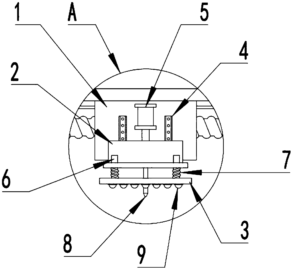
[0022] see figure 1 , in an embodiment of the present invention, a vibrating knife cutting mechanism includes a moving seat 1, a vibrating knife seat 2, an electric push rod 5 and a vibrating knife head 8, and the vibrating knife seat 2 slidingly matched with it is installed on the moving seat 1 A vibrating knife head 8 is installed on the vibrating knife seat 2, and an electric push rod 5 for driving the vibrating knife seat 2 to move is also installed on the moving seat 1. The bottom of the vibrating knife seat 2 is elastically connected with a pressure plate 3. Specifically, The pressing plate 3 is directly below the vibrating knife seat 2, and several connecting shafts 6 are fixed on the pressing plate 3, each of the connecting shafts 6 passes through the steps on the outside of the vibrating knife seat 2 and is slidably matched with the vibrating knife seat 2 , the outer sleeve of the connecting shaft 6 is provided with a spring 7, and the two ends of the spring 7 are res...

Embodiment 2

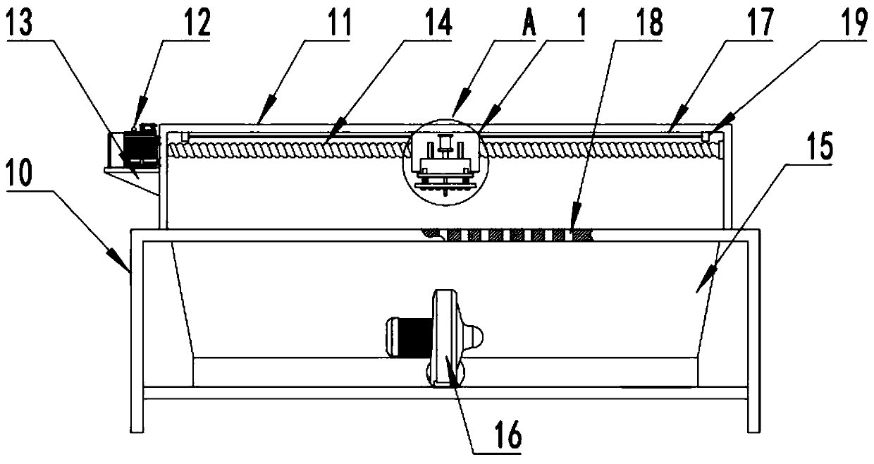
[0026] see Figure 2~3 , In the embodiment of the present invention, a cutting machine is also proposed, including the bottom bracket 10, and also includes the vibrating knife cutting mechanism as described in the above embodiment.

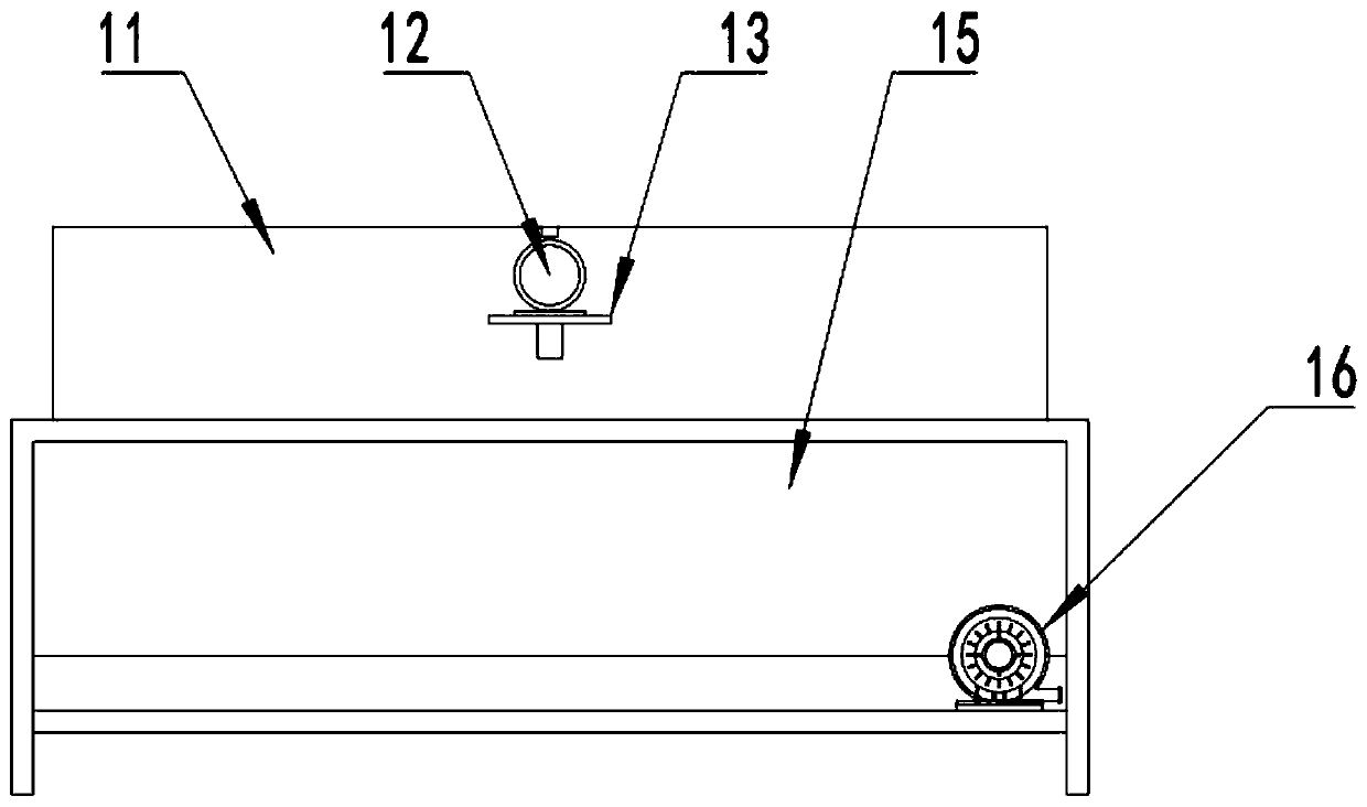
[0027] A mounting bracket 11 is fixed on the bottom bracket 10, a servo motor 12 is installed on the mounting bracket 11 through a motor mounting seat 13, a ball screw 14 is installed on the output end of the servo motor 12, and the moving seat 1 and the ball screw 14 form a spiral Auxiliary transmission, the moving base 1 is also slidingly matched with the slide rail 17 arranged on the mounting bracket 11; of course, in order to limit the stroke of the moving base 1, travel switches 19 are installed at both ends of the sliding base 17. In practical application, the moving base 1 can be subjected to the action of the servo mechanism formed by the servo motor 12 and the ball screw 14 to perform reciprocating motion to realize the adjustment of the ...


PUM


Abstract

The invention discloses a vibration tool cutting mechanism. A moving base, a vibration tool base, an electric push rod and a vibration tool bit are included. The moving base is provided with the vibration tool base which is in sliding fit with the moving base. The vibration tool base is provided with the vibration tool bit. The moving base is further provided with the electric push rod for drivingthe vibration tool base to move. The bottom of the vibration tool base is elastically connected with a pressing plate. The pressing plate is located under the vibration tool base. The vibration toolcutting mechanism has the beneficial effects that when the vibration tool bit descends, the pressing plate can make contact with a to-be-cut workpiece firstly, the workpiece is pressed, and accordingly the situation of workpiece wrinkling during cutting is prevented; during cutting, the vibration tool bit and the to-be-cut workpiece need to relatively move, in the process, due to arranged balls, the phenomenon of workpiece wrinkling due to moving is avoided, the workpiece pressing effect can be guaranteed during moving, and the motion direction of the vibration tool base is not limited by theball design.

Description

technical field [0001] The invention relates to a cutting device, in particular to a vibrating knife cutting mechanism and a cutting machine. Background technique [0002] The moving knife cutting machine is a kind of equipment that can quickly achieve efficient typesetting and achieve cutting of various materials. It is also suitable for proofing and small batch production. The production of the vibrating knife cutting machine has allowed more companies to bid farewell to the traditional manual knife cutting process Entering a new era of digital die-free processing, there is no need to make dies, which saves expenses such as die-making management in the production and development process. Nowadays, vibrating knife cutting machines have been widely used for cutting PU leather, clothing fabrics, plastic boards and straight boards. [0003] Especially for clothing fabrics, when cutting, due to the need for relative movement between the cutter head and the clothing fabric, the...

Claims


Application Information

Patent Timeline
Patent Type & Authority Applications(China)
IPC IPC(8): B26D7/08B26D7/02B26D7/18D06H7/22
CPCB26D7/025B26D7/086B26D7/1863D06H7/22
Inventor 刘明辉
Owner TIANJIN HONGGUANG WEIYE LASER TECH CO LTD
Why Eureka
Try Eureka