Punching device for paperboard

A punching device and cardboard technology, which is applied in metal processing and other directions, can solve the problem of waste cardboard detachment, and achieve the effects of avoiding offset, ensuring stability, and improving work efficiency

Pending Publication Date: 2019-07-12
武威福民汇科技开发有限公司
View PDF0 Cites 13 Cited by
  • Summary
  • Abstract
  • Description
  • Claims
  • Application Information

AI Technical Summary

Problems solved by technology

[0004] The object of the present invention is: in order to solve the problem that the waste generated when the existing cardboard is punched cannot be completely separated from the cardboard, the present invention provides a punching device for cardboard

Method used


Image

  • Punching device for paperboard
  • Punching device for paperboard
  • Punching device for paperboard

Examples


Embodiment 1

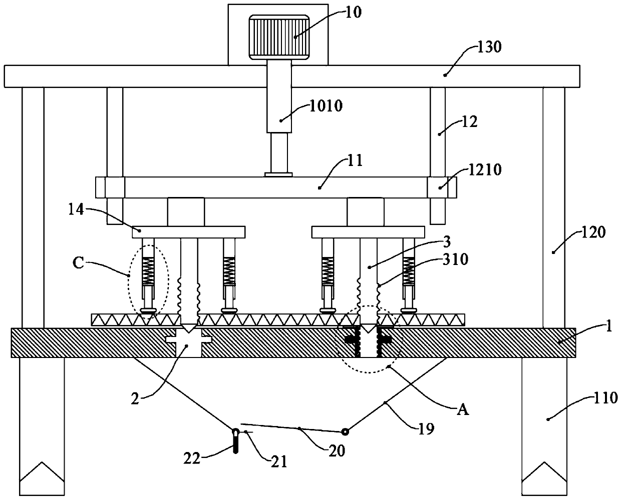
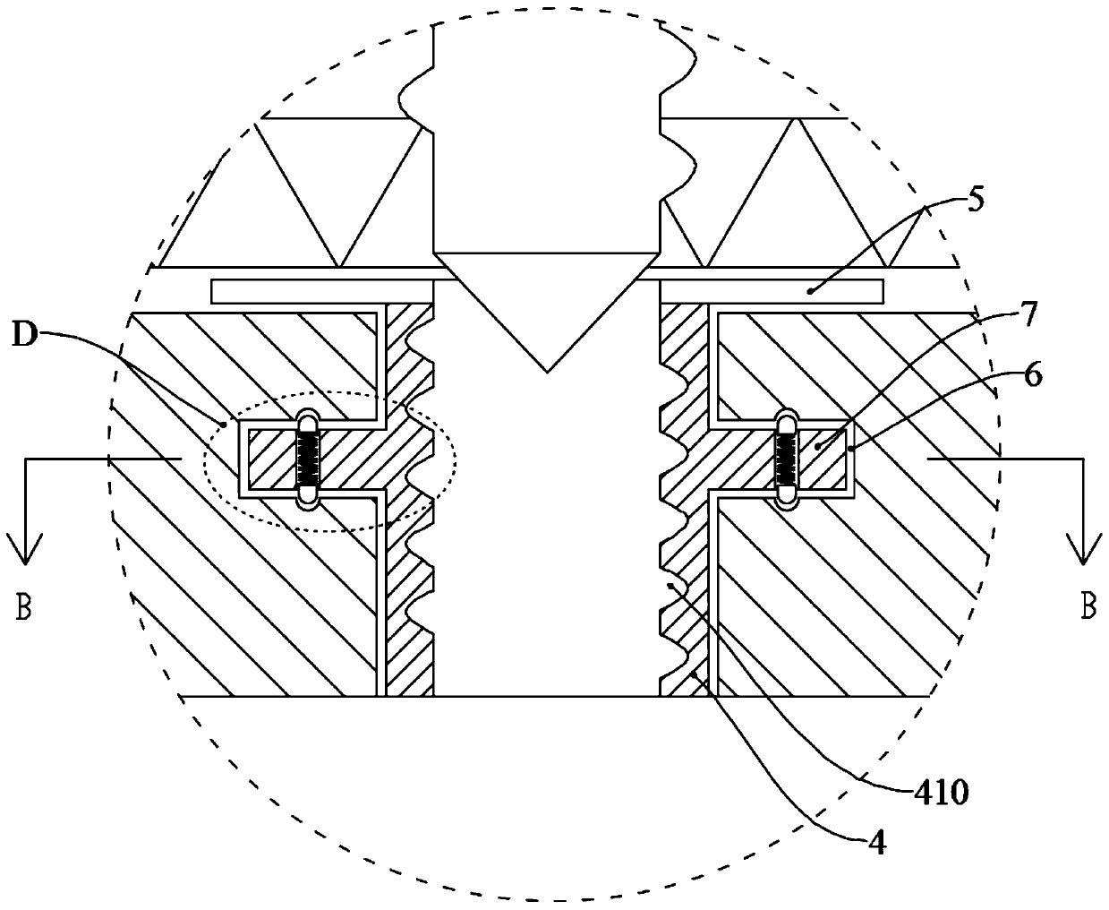
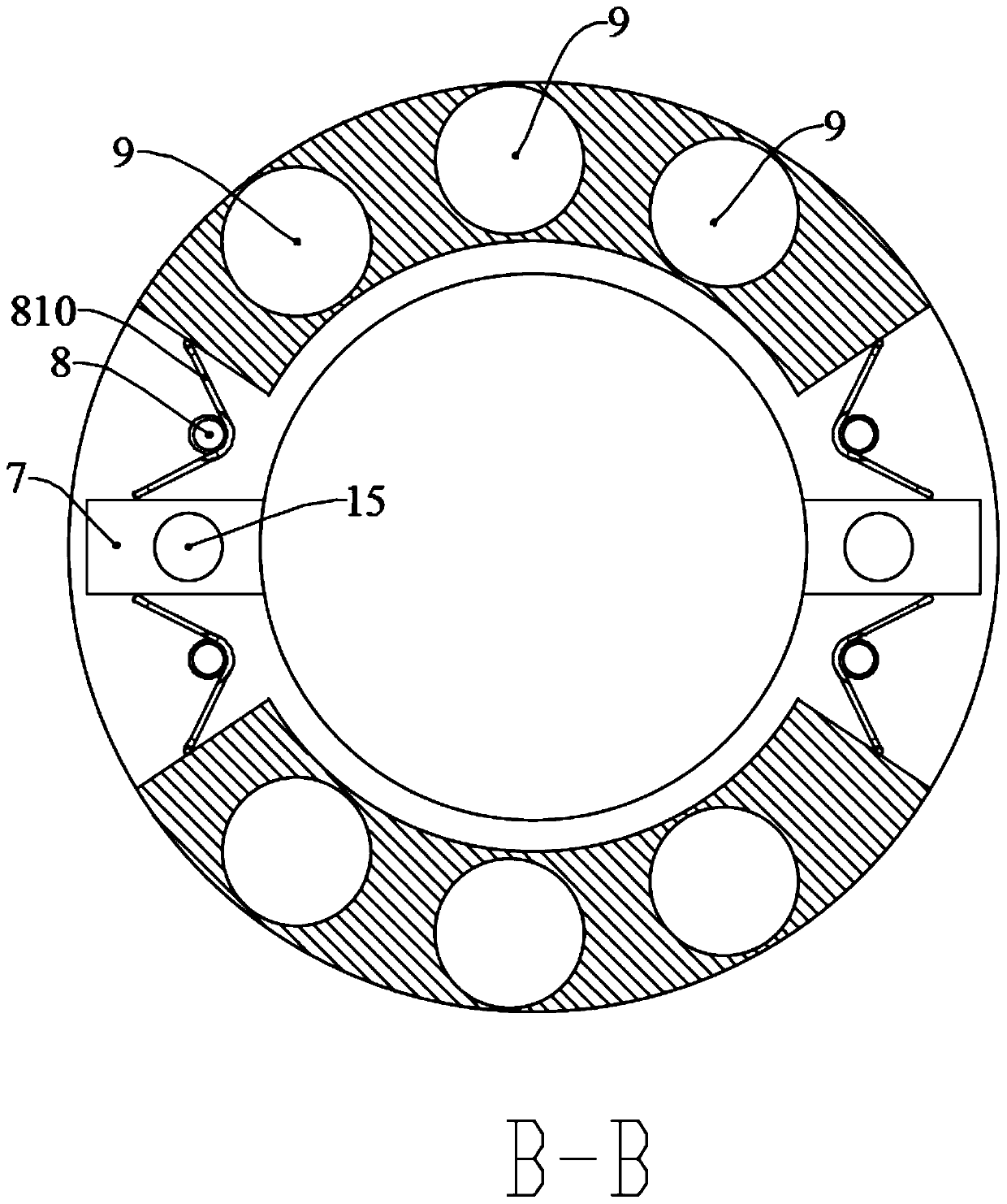
[0033] The cardboard punching device of the present invention comprises a workbench 1, which is provided with a plurality of relief holes 2 through the workbench 1, and a plurality of perforating needles 3 which can be lifted and lowered at the same time are arranged above the workbench 1; the lower ends of any perforating needles 3 The outer wall is spirally provided with reinforcing ribs 310 along the height direction, and a sleeve 4 is arranged in any relief hole 2. The inner wall of the sleeve 4 is provided with a spiral guide groove 410 matching with the reinforcing ribs 310 along the height direction. The upper end extends out of the relief hole 2 and is connected with a plurality of blades 5, the middle outer wall of the relief hole 2 is symmetrically provided with a placement groove 6, and the outer wall of the sleeve 4 is symmetrically connected with a positioning block 7 located in the placement groove 6, any positioning block 7 Both sides are provided with positionin...

Embodiment 2

[0036] This embodiment is further optimized on the basis of Embodiment 1 as follows: the lower end of the workbench 1 is provided with a plurality of supporting legs 110, the left and right sides of the upper end of the workbench 1 are provided with support plates 120, and the upper end of the support plate 120 Connected with a placement table 130, the upper end of the placement table 130 is provided with a hydraulic cylinder 10, the telescopic shaft 1010 of the hydraulic cylinder 10 runs through the placement table 130 and is connected with a lifting plate 11, and the lifting plate 11 below is connected with several punching needles 3.

[0037] After adopting the above-mentioned technical scheme, a support plate 120 and a placement platform 130 are provided on the upper end of the workbench 1, and the support plate 120, the placement platform 130 and the workbench 1 are welded or bolted to maintain integrity, and driven by the hydraulic cylinder 10. With the expansion and cont...

Embodiment 3

[0039] This embodiment is further optimized on the basis of Embodiment 2 as follows: the lower end of the placing platform 130 is also provided with a plurality of guide posts 12 , and the lifting plate 11 is provided with a plurality of guide holes 1210 for the guide posts 12 to pass through.

[0040] After the above-mentioned technical scheme is adopted, the stability of the lifting plate 11 during the lifting process is ensured through the function of the guide post 12 and the guide hole 1210, and the deviation of the punching pin 3 during the lifting process is avoided, effectively preventing the punching pin 3 from colliding with the lifting plate. The placement table 130 collides, resulting in damage to the tines 3 and potential safety hazards caused by the damage of the tines 3 .


PUM


Abstract

The invention discloses a punching device for paperboard, belongs to the technical field of paper punching devices and aims to solve the problem that waste chips generated when the paperboard is punched in an existing way cannot be completely separated from the paperboard. The punching device comprises a workbench, wherein a plurality of receding holes penetrate through the workbench, and a plurality of punching needles are arranged above the workbench; a reinforcing rib is arranged at the lower end of any punching needle; a sleeve is arranged in any receding hole; spiral guide grooves matchedwith the reinforcing ribs are formed in the inner wall of the sleeves in the height direction; the upper ends of the sleeves extend out of the receding holes to be connected with a plurality of blades; a storage groove is formed in the middle of each receding hole; positioning blocks are symmetrically connected to the outer wall of the sleeves; positioning columns are arranged on two sides of anypositioning block, and the positioning columns are sleeved with torsion springs; one end of each torsion spring is connected with the corresponding positioning block, and the other end of each torsion spring is connected with the inner wall of the corresponding storage groove; and a plurality of chip removal grooves penetrate through the periphery of any receding hole.

Description

technical field [0001] The present invention relates to the technical field of punching devices for paper products, in particular to a punching device for cardboard. Background technique [0002] Cardboard is also called cardboard. A thick paper sheet made of various pulps with interwoven fibers. When cardboard is used as a packaging material, there is a need for heat dissipation and ventilation or other needs, and it is often necessary to punch the cardboard. The existing punching device is generally provided with a through hole on the workbench. There is a punching needle that can be lifted up and down. Driven by the lifting control device, the punching needle enters into the relief hole to punch the cardboard, and the waste generated by punching the cardboard is discharged to the Collect it under the workbench. [0003] However, in the prior art, when some cardboard is punched by punching, the waste at the through hole of the cardboard will not be directly separated fr...

Claims


Application Information

Patent Timeline
Patent Type & Authority Applications(China)
IPC IPC(8): B26F1/24B26D1/29B26D7/18B26D7/20B26D7/02
CPCB26D1/295B26D7/025B26D7/18B26D7/20B26F1/24
Inventor 赵映翔毕兆阳林思瑶
Owner 武威福民汇科技开发有限公司
Why Eureka
Try Eureka