Variable speed ratio steering system based on cross shaft universal joint

A cross-shaft universal and steering system technology, applied in the field of variable-speed ratio steering systems, can solve the problems of high manufacturing cost and time-consuming manufacturing, and achieve the effects of simple structure, reduced manufacturing cost, and improved steering portability.

Active Publication Date: 2020-08-04
CHONGQING UNIV
View PDF5 Cites 0 Cited by
  • Summary
  • Abstract
  • Description
  • Claims
  • Application Information

AI Technical Summary

Problems solved by technology

However, the manufacture of these structures needs to change the structure of the meshing teeth, which makes the manufacture time-consuming, the manufacturing cost is high, and it is not easy to make continuous and smooth changes in the speed ratio, such as attached Figure 13 shown

Method used


Image

  • Variable speed ratio steering system based on cross shaft universal joint
  • Variable speed ratio steering system based on cross shaft universal joint
  • Variable speed ratio steering system based on cross shaft universal joint

Examples


Embodiment 1

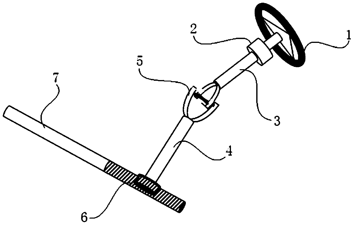
[0039] see figure 1 and figure 2 , the present embodiment discloses a variable speed ratio steering system based on cross-axis universal joints, including a steering wheel 1, a primary reduction mechanism 2, a steering column 3, a cross-axis universal joint transmission mechanism, a steering transmission shaft 4 and a steering gear.

[0040] The primary reduction mechanism 2 is a primary constant speed ratio reducer. The input end of the primary reduction mechanism 2 is connected to the output end of the steering wheel 1 , and the output end of the primary reduction mechanism 2 is connected to the input end of the steering column 3 . That is, the input shaft of the primary constant speed reducer is connected to the output shaft of the steering wheel 1 , and the output shaft of the primary constant speed reducer is connected to the input shaft of the steering column 3 .

[0041] The angle at which the steering column 3 rotates is recorded as When the steering wheel 1 is i...

Embodiment 2

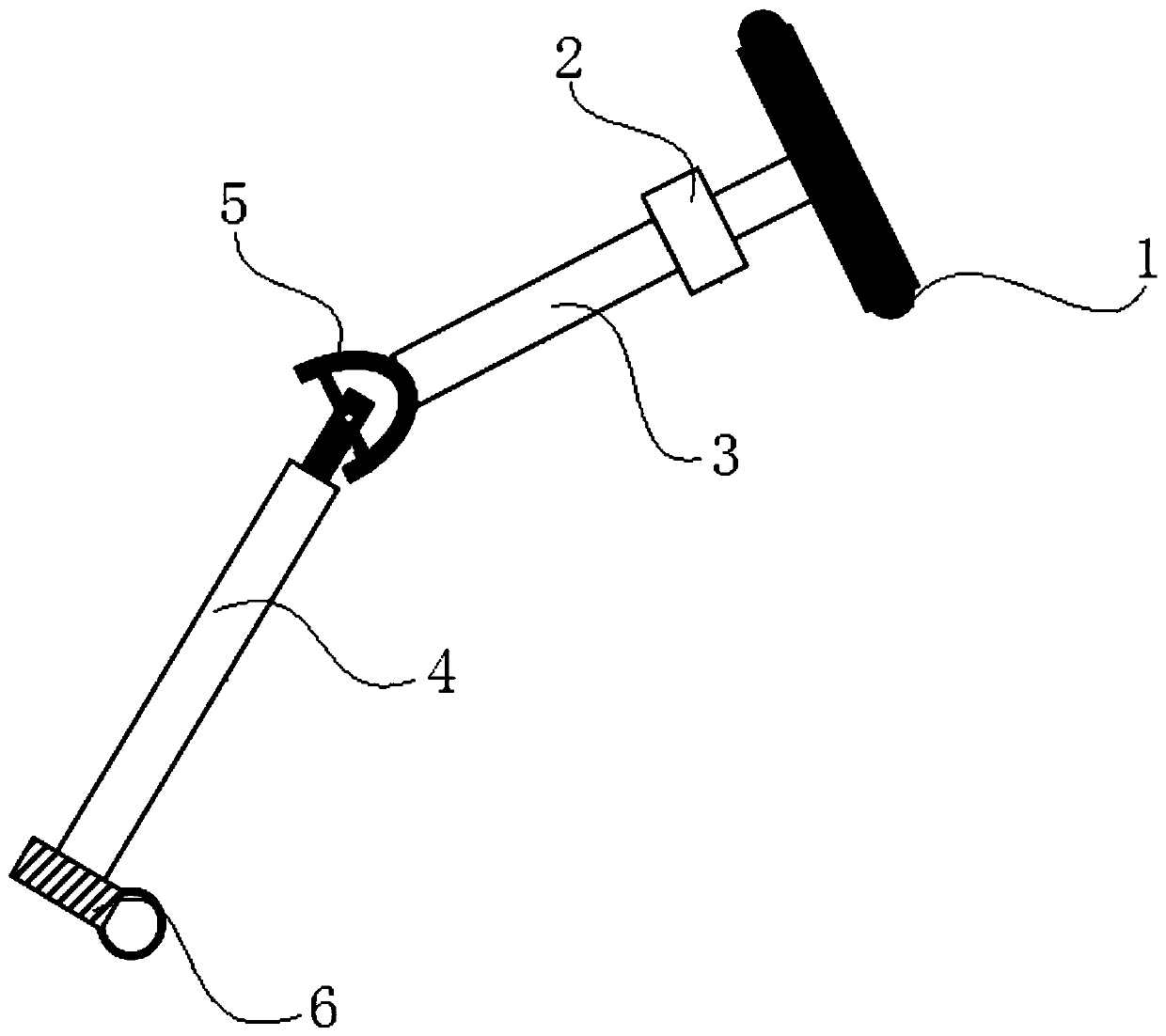
[0055] see image 3 and Figure 4 , the present embodiment discloses a variable speed ratio steering system based on cross-axis universal joints, including a steering wheel 1, a primary reduction mechanism 2, a steering column 3, a cross-axis universal joint transmission mechanism, a steering transmission shaft 4 and a steering gear.

[0056] The primary reduction mechanism 2 is a primary constant speed ratio reducer. The input end of the primary reduction mechanism 2 is connected to the output end of the steering wheel 1 , and the output end of the primary reduction mechanism 2 is connected to the input end of the steering column 3 . That is, the input shaft of the primary constant speed reducer is connected to the output shaft of the steering wheel 1 , and the output shaft of the primary constant speed reducer is connected to the input shaft of the steering column 3 .

[0057] The angle at which the steering column 3 rotates is recorded as When the steering wheel 1 is in...

Embodiment 3

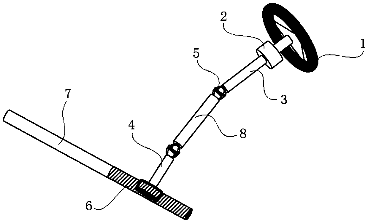
[0072] see Figure 5 and Figure 6 , the present embodiment discloses a variable speed ratio steering system based on cross-axis universal joints, including a steering wheel 1, a primary reduction mechanism 2, a steering column 3, a cross-axis universal joint transmission mechanism, a steering transmission shaft 4 and a steering gear.

[0073] The primary reduction mechanism 2 is a primary constant speed ratio reducer. The input end of the primary reduction mechanism 2 is connected to the output end of the steering wheel 1 , and the output end of the primary reduction mechanism 2 is connected to the input end of the steering column 3 . That is, the input shaft of the primary constant speed reducer is connected to the output shaft of the steering wheel 1 , and the output shaft of the primary constant speed reducer is connected to the input shaft of the steering column 3 .

[0074] The angle at which the steering column 3 rotates is recorded as When the steering wheel 1 is i...


PUM


Abstract

The invention discloses a variable gear ratio steering system based on a lardan university joint. The variable speed ratio steering system comprises a steering wheel, a first-stage speed reduction mechanism, a steering pipe column, a lardan university joint transmission mechanism, a steering transmission shaft and a steering gear. The first-stage speed reduction mechanism is a first-stage fixed speed ratio speed reducer, the input end of the first-stage speed reduction mechanism is connected with the output end of the steering wheel, and the output end of the first-stage speed reduction mechanism is connected with the input end of the steering pipe column. The lardan university joint transmission mechanism comprises a lardan university joint kinematic pair, the input end of the lardan university joint kinematic pair is connected with the output of the steering pipe column, and the output end of the lardan university joint kinematic pair is connected with the input end of the steering transmission shaft. The steering gear is a fixed speed ratio steering gear, and the steering gear is connected to the output end of the steering transmission shaft. The variable gear ratio steering system is simple in structure, and the speed ratio can be continuously and smoothly changed, therefore, the manufacturing cost can be reduced, and the steering smoothness of an automobile can be improved.

Description

technical field [0001] The invention belongs to the field of automobile steering systems, in particular to a variable speed ratio steering system based on cross shaft universal joints. Background technique [0002] The variable speed ratio function of the automobile steering system is an important function to improve the driver's steering experience. When the car is turning sharply at low speed, the steering resistance torque is large, so the speed ratio of the steering system is required to be large to improve the portability of steering; when the car is turning at a high speed, the steering wheel angle is small, and the steering resistance torque is also small. When the steering wheel is required to be responsive, the speed ratio of the steering system should be smaller. Therefore, the speed ratio change curve of the steering system should be selected as a concave curve with a smaller middle and a larger two ends. Currently widely used steering gears with variable speed ...

Claims


Application Information

Patent Timeline
Patent Type & Authority Patents(China)
IPC IPC(8): B62D3/02B62D7/18
CPCB62D3/02B62D7/18
Inventor 鲁红伟张志飞赖旭东徐中明贺岩松
Owner CHONGQING UNIV
Why Eureka
Try Eureka