Efficient ultrahigh-molecular-weight polyethylene fiber drying device

An ultra-high molecular weight, drying device technology, applied in the direction of rayon cleaning/drying, etc., can solve the problems of uneven heating of materials, affecting the drying rate of materials, etc., and achieve the effect of improving heat utilization efficiency and reducing drying efficiency.

Inactive Publication Date: 2019-07-12
JIULI ROPE
View PDF2 Cites 2 Cited by
  • Summary
  • Abstract
  • Description
  • Claims
  • Application Information

AI Technical Summary

Problems solved by technology

The drying box in this patent needs to export air, and the temperature at the air outlet is low, which leads to uneven heating of materials
[0004] The existing patent number is CN105806071A, which discloses a new type of drying box, including the main body of the drying box, the air outlet pipe, the heating device, the dehumidification device, the purification device, the fan, the air inlet pipe, the moisture absorption layer, and the heat preservation layer , air flow sensor, blower, fabric, plastic curtain, temperature sensor, computer, roller, cloth inlet, cloth outlet, the humid hot air in the patented drying box is easy to accumulate in the corner of the drying box, affecting the material drying rate

Method used


Image

  • Efficient ultrahigh-molecular-weight polyethylene fiber drying device
  • Efficient ultrahigh-molecular-weight polyethylene fiber drying device
  • Efficient ultrahigh-molecular-weight polyethylene fiber drying device

Examples


Embodiment 1

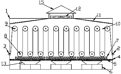
[0023] Example 1: When in use, the polyethylene extraction wire enters the box body 1 through the wire inlet 2, bypasses between the lower guide roller 8 and the upper guide roller 9 and passes through the wire outlet 3, the heating pipe 7 and the circulating fan 6 Start to work and burn to generate hot air, which flows inside the box 1 under the action of the circulating fan 6, and the hot air carrying water vapor flows to the inner top surface of the box 1. When the water vapor gathers into water droplets, the deflector 11 guides the water droplets to flow along the inner wall of the box 1 , to avoid that when the top surface of the box body 1 is flat, water droplets accumulate and directly drip onto the polyethylene wire, which will affect the drying effect.

Embodiment 2

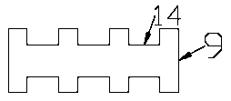
[0024] Embodiment 2: The upper guide roller 9 and the lower guide roller 8 are provided with card slots 14 at intervals, according to the polyethylene extraction wires are placed in the card slots 14 at intervals, and the slots 14 are placed with polyethylene extraction wires at intervals to prevent the upper guide roller 9 from And the lower guide roller 8 is segregated to one side during the rotation of the polyethylene extraction wire, thereby affecting the drying efficiency.


PUM


Abstract

The invention relates to the technical field of polyethylene fiber production equipment, in particular to an efficient ultrahigh-molecular-weight polyethylene fiber drying device which comprises a chamber. The lower portion of the left wall of the chamber is penetratingly provided with a fiber inlet, the lower portion of the right wall of the chamber is penetratingly provided with a fiber outlet,a partition plate with vent holes is arranged in the chamber, and circulating fans are arranged between the partition plate and the inner bottom of the chamber. Heating tubes are arranged on the top face of the partition plate, lower guide rollers are arranged above the partition plate, upper guide rollers are arranged between the lower guide rollers and the inner top face of the chamber, a gap isreserved between every two adjacent upper guide rollers, and the lower guide rollers are positioned below the gaps. Flow guide plates are arranged on the top face of the chamber, and an exhaust fan is arranged on the top face of the chamber. By the partition plate, broken polyethylene fibers are prevented from falling into the circulating fans; heat utilization efficiency is improved by the circulating fans; by corresponding arrangement of the heating tubes and the circulating fans, accumulation of heat at the partition plate can be prevented; by the flow guide plates, damp hot air can be guided to the exhaust fan, and condensate water can be guided to flow down along the inner wall of the chamber by the tangential flow guide plates.

Description

technical field [0001] The invention relates to the technical field of polyethylene fiber production equipment, in particular to a drying device for efficiently drying ultra-high molecular weight polyethylene filaments. Background technique [0002] At present, the drying oven widely used in the production of polyethylene fiber on the market mainly uses an oven to dry the material, and the air is heated and introduced into the oven for drying. This method has poor uniformity in the drying process, and the outside of the oven There is no insulation layer, resulting in more heat loss. Another way is to set the heating wire on the outside of the drying oven, and increase the temperature in the oven by heating the heating wire, so as to achieve the purpose of drying. However, due to the distance between the heating wire and the inner wall of the oven Recently, the heat generated is sharply concentrated on the inner wall of the oven. If the temperature is not well controlled, the...

Claims


Application Information

Patent Timeline
Patent Type & Authority Applications(China)
IPC IPC(8): D01D10/06
CPCD01D10/06
Inventor 王依民姜文松冯百明朱志领汤国成
Owner JIULI ROPE
Why Eureka
Try Eureka