Exhaust device for pouring steel pipe concrete and its construction method

A technology of steel pipe concrete and exhaust device, which is applied in the direction of construction, building structure, and building material processing, etc., which can solve the problems of uneven concrete pouring, uneven concrete pouring, uneven stress and force, etc., and achieve increased construction Difficulty, manpower saving, and low construction cost

Active Publication Date: 2021-07-09
CHINA CONSTR SECOND BUREAU INSTALLATION ENG +1
View PDF0 Cites 0 Cited by
  • Summary
  • Abstract
  • Description
  • Claims
  • Application Information

AI Technical Summary

Problems solved by technology

[0003] The purpose of the present invention is to provide a steel pipe concrete pouring exhaust device and its construction method, to solve the problems of complicated construction, uneven concrete pouring, uneven concrete pouring and vent holes in the steel column wall when pouring concrete in the traditional construction method There is a technical problem of uneven local stress

Method used


Image

  • Exhaust device for pouring steel pipe concrete and its construction method
  • Exhaust device for pouring steel pipe concrete and its construction method
  • Exhaust device for pouring steel pipe concrete and its construction method

Examples


Embodiment Construction

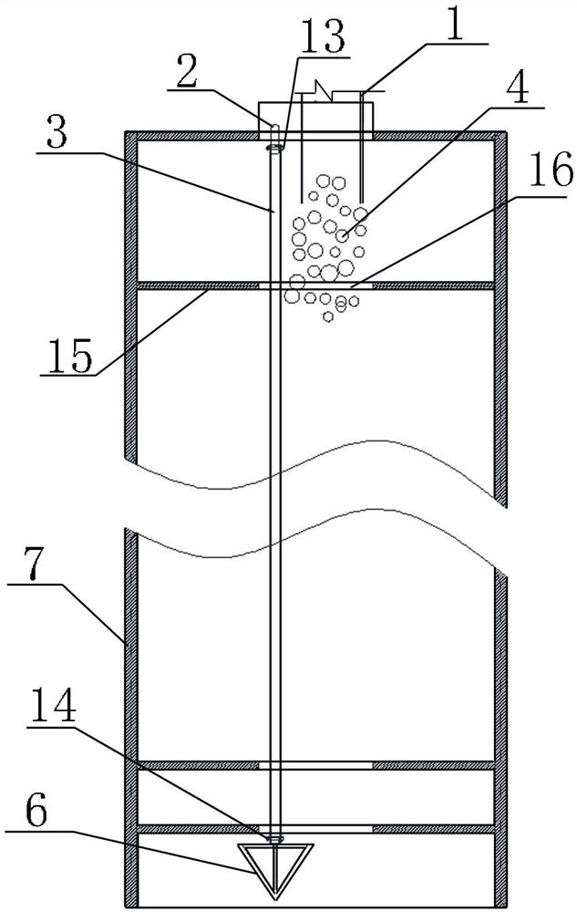
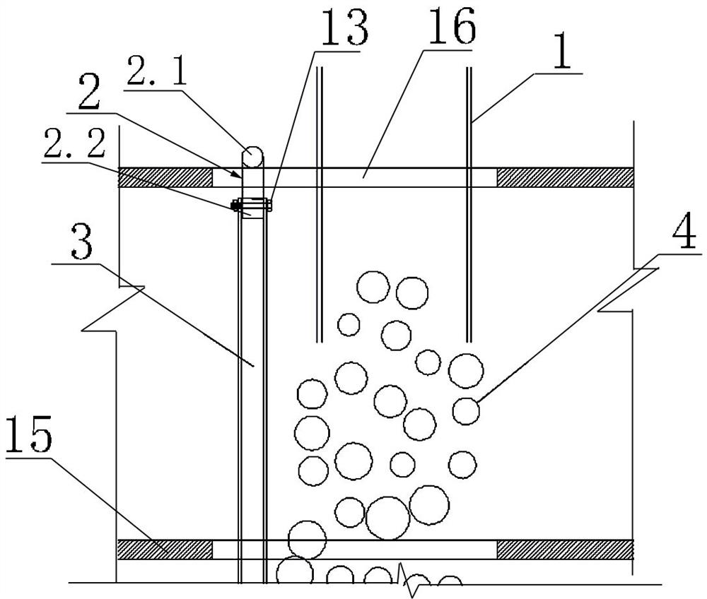
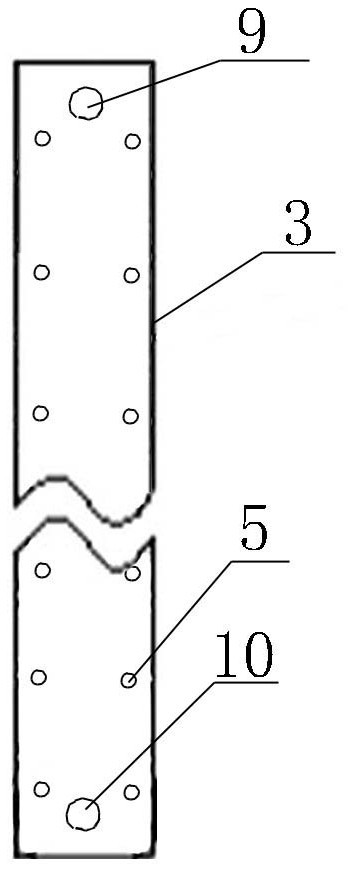
[0035] In the present embodiment, when the steel pipe concrete is pouring, the intimate and uniformity of concrete grout is realized by the exhaust device. The lower cone 6 of the exhaust pipe device uses the weight of the entire device to prevent the exhaust pipe 3. Tilt; at the top of the exhaust pipe 3 is connected to the fixing frame 2 by the bolt 2, the horizontal position of the exhaust pipe device is determined by the fixing frame 2, and the concrete pouring, the exhaust hole 5 on the exhaust pipe 3 is from the inside. The outer gradual tilt is gradually tilted to prevent the exhaust hole 5 from being blocked during concrete, and the vent hole 5 guides the column bottom air from being discharged in the exhaust pipe 3 until the grout is completed.

[0036] Such as Figure 1-8 As shown, such a steel pipe concrete pouring exhaust device is disposed in the pipe of the steel pipe 7; including a fixing frame 2, an exhaust pipe 3, and a lower cone 6; the fixing frame 2 is T-shaped,...


PUM


Abstract

A steel pipe concrete pouring exhaust device and its construction method, including a fixed frame, an exhaust pipe and a lower cone head; the fixed frame is T-shaped, including a horizontal bar and a vertical bar; Inserted in the steel pipe, the length of the exhaust pipe is adapted to the height of the concrete to be poured; the upper end of the exhaust pipe is sleeved on the vertical bar, and is connected with the vertical bar through the first bolt; on the wall of the exhaust pipe, There are exhaust holes spaced apart vertically, and the exhaust holes are inclined holes that gradually slope downward from the inside to the outside; the lower cone head is set at the bottom of the exhaust pipe and is conical; the tip of the lower cone head faces downward ; There is a connecting short rod in the middle of the top of the lower cone head; the connecting short rod is plugged into the lower end of the exhaust pipe and connected with the exhaust pipe through the second bolt. The invention solves the technical problems of cumbersome construction, uneven concrete pouring, uneven concrete pouring and uneven local stress at the vent hole of the steel column wall existing in the traditional construction method of pouring concrete.

Description

Technical field [0001] The invention belongs to the field of civil engineering, in particular a steel pipe concrete pouring exhaust device and its construction method thereof. Background technique [0002] With the rapid development of the construction industry, people also have a large demand for structures, and the steel pipe concrete structures come to life, and steel pipe concrete combination is an efficient material composite technology method, which can improve the load carrying capacity, toughness and durability of concrete. Sex. However, when the steel pipe concrete is poured, it is necessary to ensure the transmissibility of concrete, in response to this situation, the prior art opens gas hole on the steel column wall, and there is more inconvenient and risk in the steel column wall. First, when the steel column has a large wall thickness, regardless of the cumbersome process in the factory or on-site opening; two, due to the discharge gas hole on the steel column, 100mm...

Claims


Application Information

Patent Timeline
Patent Type & Authority Patents(China)
IPC IPC(8): E04G21/06
CPCE04G21/06
Inventor 郝海龙苗兴光许兴年罗军伟梁延斌
Owner CHINA CONSTR SECOND BUREAU INSTALLATION ENG
Why Eureka
Try Eureka