
Integrated electro-hydraulic servo drive hydraulic system

A hydraulic system and electro-hydraulic servo technology, applied in servo motors, servo motor components, fluid pressure converters, etc., can solve the problem that the hydraulic system cannot provide an integrated electro-hydraulic servo driver, does not have the ability to work for a long time, and the system generates a large amount of heat. and other problems, to achieve the effect of saving motor startup time, low energy loss, and low energy loss

Active Publication Date: 2017-06-30
THE GENERAL DESIGNING INST OF HUBEI SPACE TECH ACAD
View PDF1 Cites 0 Cited by
  • Summary
  • Abstract
  • Description
  • Claims
  • Application Information

AI Technical Summary

Problems solved by technology

The pump-valve joint control EHA system proposed by Beijing University of Aeronautics and Astronautics, because the servo valve is always open during operation, the throttling control of the servo valve makes the system generate a lot of heat, which seriously affects the working time and does not have the ability to work for a long time
In addition, the Chinese patent application with the application number CN201110381971.1 discloses a multidisciplinary modeling method based on the electrohydrostatic actuation system, but this modeling method cannot provide a practically applicable integrated electro-hydraulic servo drive hydraulic system

Method used


Image

  • Integrated electro-hydraulic servo drive hydraulic system
  • Integrated electro-hydraulic servo drive hydraulic system
  • Integrated electro-hydraulic servo drive hydraulic system

Examples


Embodiment Construction

[0028] In order to make the object, technical solution and advantages of the present invention clearer, the present invention will be further described in detail below in conjunction with the accompanying drawings and embodiments. It should be understood that the specific embodiments described here are only used to explain the present invention, not to limit the present invention. In addition, the technical features involved in the various embodiments of the present invention described below can be combined with each other as long as they do not constitute a conflict with each other.

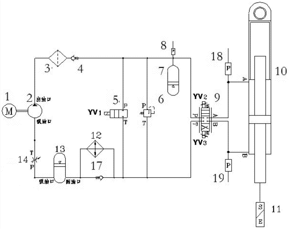
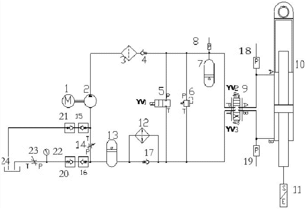
[0029] figure 1 It is a schematic structural diagram of the hydraulic system of the integrated electro-hydraulic servo driver in the embodiment of the present invention. It can be seen from the figure that the hydraulic system of the integrated electro-hydraulic servo driver of the present invention includes a driving motor 1, a hydraulic pump 2, a high-pressure filter 3, First one-way valve 4,...


PUM


Abstract

The invention discloses an integrated electro-hydraulic servo driver hydraulic system which comprises a drive motor, a hydraulic pump, a first check valve, a second check valve, an electromagnetic reversing valve, an overflow valve, a servo valve, a hydraulic cylinder, a sealed boosting oil tank and a first throttling valve. The drive motor is connected with the hydraulic pump. The oil outlet of the hydraulic pump is connected with the first check valve. The first check valve is divided into three liquid ways at the same time. The first liquid way is connected with the port P of the electromagnetic reversing valve. The port T of the electromagnetic reversing valve is connected with the second check valve. The second liquid way is connected with the port P of the overflow valve. The port T of the overflow valve is connected with the second check valve. The third liquid way is connected with the port P of the servo valve. The port T of the servo valve is connected with the second check valve. The port A and the port B of the servo valve are communicated with the port A and the port B of the hydraulic cylinder respectively. The second check valve is sequentially connected with the sealed boosting oil tank and the port P of the first throttling valve. The port T of the first throttling valve is connected with the oil sucking opening of the hydraulic pump. The hydraulic system is not prone to heating and can stand by for a long time.

Description

technical field [0001] The invention belongs to the hydraulic field, and more specifically relates to a high-precision, high-frequency-response special hydraulic system suitable for use in limited spaces such as aviation and aerospace. The hydraulic system is the main component of an integrated electro-hydraulic servo drive . Background technique [0002] The integrated electro-hydraulic servo drive combines the advantages of the traditional hydraulic drive system and the direct drive system of the motor, and has the ability of high torque and high power density. It is controlled by a servo valve and has a high response frequency. [0003] Developed countries such as the United States and Europe often use high-frequency response motors to directly drive hydraulic pumps, which are called integrated electric hydrostatic actuators (EHA for short). The pump-valve joint control EHA system proposed by Beijing University of Aeronautics and Astronautics, because the servo valve is ...

Claims


Application Information

Patent Timeline
Patent Type & Authority Patents(China)
IPC IPC(8): F15B11/08F15B13/06F15B3/00F15B1/04
CPCF15B1/04F15B3/00F15B11/08F15B13/04
Inventor 王辉雷建红张延平雷勇杰郭绍波谢瑜娴熊俊
Owner THE GENERAL DESIGNING INST OF HUBEI SPACE TECH ACAD
Learn More