
Light-emitting system with free floating appearance

A technology of light-emitting components and light-emitting surfaces, which is applied to semiconductor devices of light-emitting components, organic semiconductor devices, components of lighting devices, etc., can solve problems such as damage to visual and visual visibility, difficulty in inspection costs, etc. Simple and more cost-effective to manufacture/assemble, durable lighting system

Active Publication Date: 2019-07-12
ZKW GRP GMBH
View PDF7 Cites 0 Cited by
  • Summary
  • Abstract
  • Description
  • Claims
  • Application Information

AI Technical Summary

Problems solved by technology

In particular, the free-floating look is compromised by the visibility of the electrical connections or frames, wiring has to be laid and fastened and a significant number of plugs and electrical connections are necessary, which have to be fitted, are difficult to inspect and thus cause cost

Method used


Image

  • Light-emitting system with free floating appearance
  • Light-emitting system with free floating appearance
  • Light-emitting system with free floating appearance

Examples


Embodiment Construction

[0046] It is obvious that the embodiments described here are only for illustration and are not to be interpreted as restrictive to the invention; Within the protection scope of the invention, the protection scope is determined by the claims.

[0047] In the figures, the same reference signs are used for the same or similar elements for the purpose of simpler explanation and illustration. Reference signs used in the claims shall otherwise only facilitate the readability of the claims and the understanding of the invention and shall in no way have features that impair the scope of protection of the invention.

[0048] It should be noted that all the examples shown in the figures can be arranged in and are part of a motor vehicle headlight.

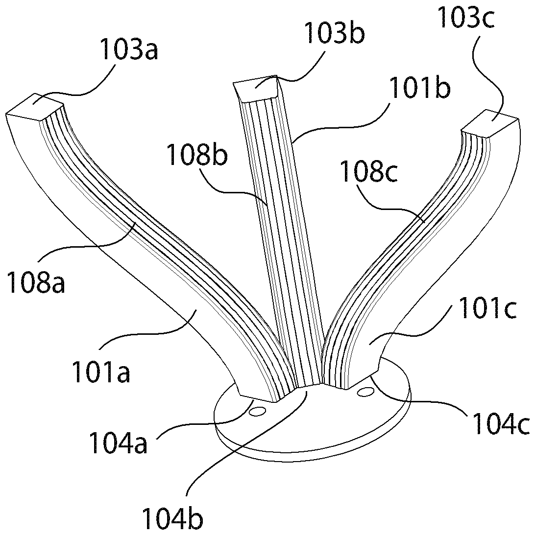
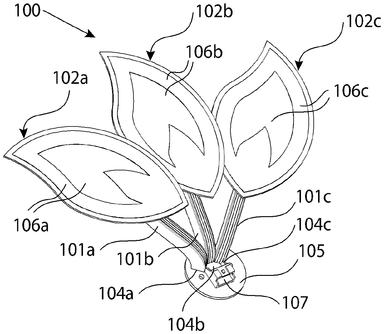
[0049] figure 1 A perspective view of an exemplary lighting assembly 100 according to the present invention is shown. The lighting assembly 100 comprises a total of three slightly elongated and pivoting supports 101a, 101b, 101c of differ...


PUM


Abstract

The invention relates to a light-emitting assembly. The assembly comprises at least one bracket and a surface light source arranged on the bracket, wherein the surface light source comprises at leastone light-emitting surface and a back surface opposite to the at least one light-emitting surface; wherein a contact surface is arranged on the rear surface and the surface light source is mechanically and electrically connected to at least one support at the contact surface, and wherein the support comprises a metal conductor line for the electrical contact connection of the surface light source,said metal conductor line being printed on the support with a conductive ink. Furthermore, the invention relates to a lighting device for a motor vehicle, in particular a motor vehicle headlamp, comprising at least one such light-emitting assembly.

Description

technical field [0001] The invention relates to a lighting assembly comprising at least one support and a surface light source (Leuchte) arranged at the support, wherein the surface light source comprises at least one luminous surface and a back facing away from the at least one luminous surface, wherein A contact surface is arranged on the rear side and the area light source is mechanically and electrically connected to at least one carrier at the contact surface. Background technique [0002] Surface light sources, such as especially organic light-emitting diodes (OLEDs), are particularly suitable for new customer-specific design requirements due to their homogeneous radiation characteristics, small structural space depth, almost arbitrary shape and the possibility of segmenting, such as For example with regard to the special luminous look (Leuchteindruck) for showing depth effects and for achieving free-floating appearances (schwebende Erscheinungsbild). The presentation...

Claims


Application Information

Patent Timeline
Patent Type & Authority Applications(China)
IPC IPC(8): F21S41/155F21S41/19F21S43/145F21S43/19F21V23/00F21W102/00F21W103/00F21Y115/15
CPCF21S41/155F21S41/192F21S43/145F21S43/195F21V23/001F21Y2115/15F21W2102/00F21W2103/00F21V21/35H01R4/04F21S2/005F21V23/002
Inventor J.古图A.霍兹
Owner ZKW GRP GMBH
Learn More