Electric valve and welding process thereof

A welding process and electric power technology, which is applied in the field of electric valves and their welding processes, can solve the problems of unfavorable remote control, inconvenience, unfavorable long-term use of valves, etc., and achieve the effect of improving welding effect, benefiting long-term use, and increasing stress

Inactive Publication Date: 2019-07-16
NANTONG LIPEI FLUID VALVE IND CO LTD
View PDF5 Cites 3 Cited by
  • Summary
  • Abstract
  • Description
  • Claims
  • Application Information

AI Technical Summary

Problems solved by technology

Valves used in fluid control systems, from the simplest globe valves to various valves used in extremely complex automatic control systems, have a wide variety of varieties and specifications. According to their functions, they can be divided into shut-off valves, check valves, and regulating valves. valves, etc.; however, the existing valves are mostly opened and closed manually, which is inconvenient and not conducive to remote control. Without electric opening and closing components, the opening and closing of the valve and convenient flow control cannot be realized; the valve is often installed outside and is easily damaged. Rainwater erosion is not conducive to the long-term use of the valve; the welding process in the production process of the existing valve is relatively simple, and the weld seam welded at the valve neck seat is a "V"-shaped groove; this structure is prone to stress cracks that affect the later valve. use, and the selection of welding equipment in the early stage of the valve welding process and the treatment of the weld seam of the valve body after welding are not perfect, which affects the welding effect of the valve

Method used


Image

  • Electric valve and welding process thereof
  • Electric valve and welding process thereof
  • Electric valve and welding process thereof

Examples


Embodiment Construction

[0028] The following will clearly and completely describe the technical solutions in the embodiments of the present invention with reference to the accompanying drawings in the embodiments of the present invention. Obviously, the described embodiments are only some, not all, embodiments of the present invention. Based on the embodiments of the present invention, all other embodiments obtained by persons of ordinary skill in the art without making creative efforts belong to the protection scope of the present invention.

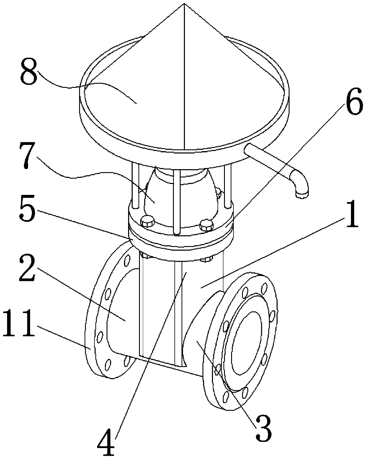
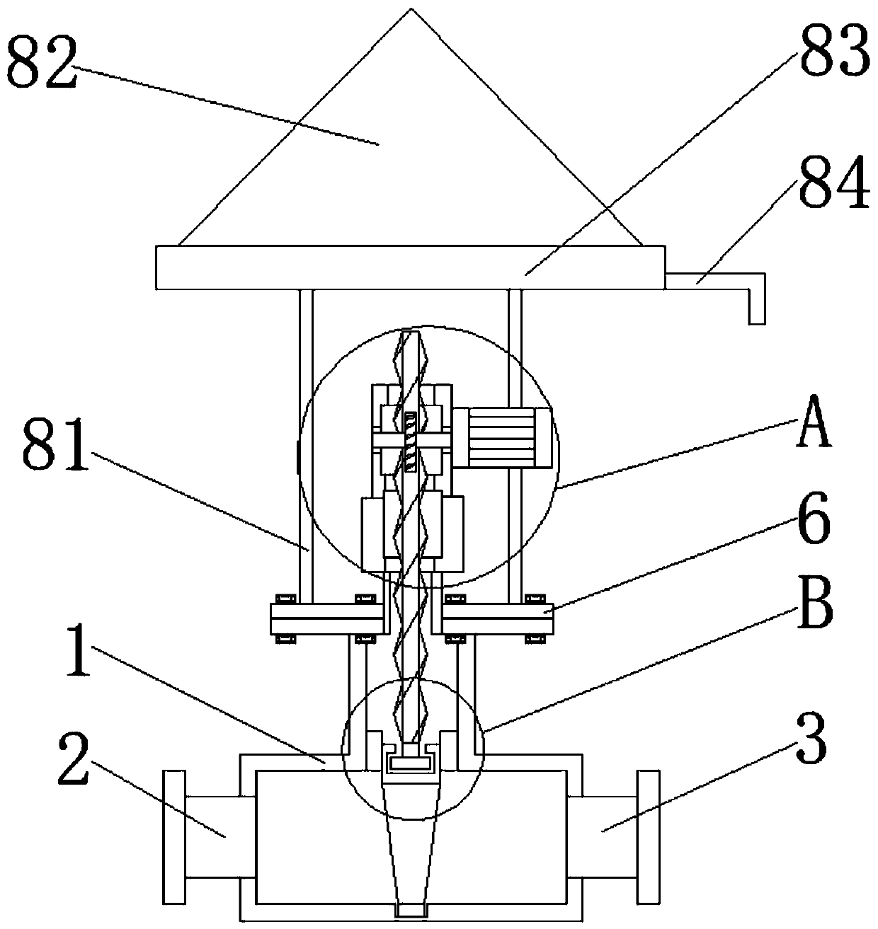
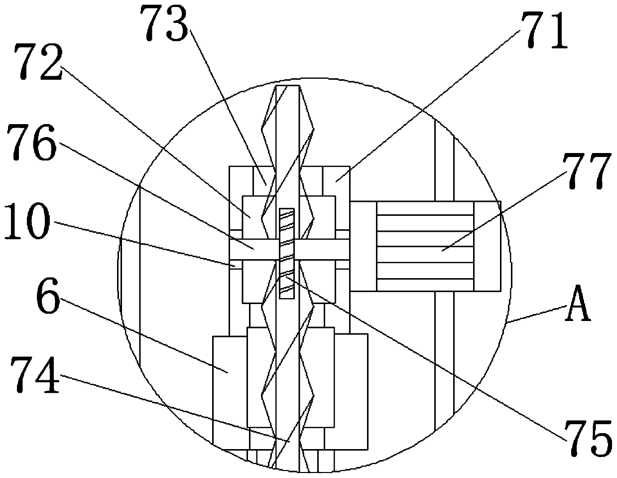
[0029] see Figure 1-4 , the present invention provides a technical solution: an electric valve, including a valve body 1, a water inlet pipe 2, a water outlet pipe 3, a valve neck seat 4, a mounting flange 5, a valve cover 6, an electric opening and closing assembly 7, and a water retaining assembly 8. The gate 9, the bearing 10 and the connecting flange 11, the water inlet pipe 2 is welded through the outer wall of the bottom end of one side of the valve bod...


PUM


Abstract

The invention discloses an electric valve and a welding process thereof. The electric valve comprises a valve body, a water inlet pipe, a water outlet pipe, a valve neck seat, a mounting flange, a valve deck, an electric opening and closing assembly, a water baffle assembly, a flashboard, a bearing and a connection flange; the water inlet pipe is welded to the outer wall of the bottom end of one side of the valve body in a through mode; and the water outlet pipe is welded to the outer wall of one side, opposite to the water inlet pipe, of the valve body in a through mode. The electric valve achieves vertical movement of the flashboard inside the valve body through arrangement of the electric opening and closing assembly, electric opening and closing and flow control over the valve are achieved, remote control over the valve is achieved through electricity, and the purpose of the valve is wide; through arrangement of the water baffle assembly, atop cover is conical to prevent rain for the valve, rain corrosion on the valve is reduced, and long-time use of the valve is facilitated; according to the welding process of the electric valve, a weld joint welded at the valve neck seat is aU-type groove; and the structure increases the stress of the valve, the welding effect of the valve is improved, and the quality of the valve is improved.

Description

technical field [0001] The invention relates to the technical field of valves, in particular to an electric valve and its welding process. Background technique [0002] The valve is a control component in the fluid delivery system, which has functions such as cut-off, adjustment, flow diversion, reverse flow prevention, pressure stabilization, flow diversion or overflow pressure relief. Valves used in fluid control systems, from the simplest globe valves to various valves used in extremely complex automatic control systems, have a wide variety of varieties and specifications. According to their functions, they can be divided into shut-off valves, check valves, and regulating valves. valves, etc.; however, the existing valves are mostly opened and closed manually, which is inconvenient and not conducive to remote control. Without electric opening and closing components, the opening and closing of the valve and convenient flow control cannot be realized; the valve is often ins...

Claims


Application Information

Patent Timeline
Patent Type & Authority Applications(China)
IPC IPC(8): F16K3/12F16K31/04F16K27/12B23P15/00
CPCB23P15/001F16K3/0254F16K3/12F16K27/12F16K31/047
Inventor 于亚平鞠昌平王芳
Owner NANTONG LIPEI FLUID VALVE IND CO LTD
Why Eureka
Try Eureka