
Device and method for driving injection type refrigerating system through automobile waste heat recovery

A technology for waste heat recovery and refrigeration system, which is applied to machines, refrigerators, and refrigeration components that use waste heat. It can solve problems such as low efficiency and insufficient waste heat recovery, and achieve the effect of saving fuel and meeting the needs of low-temperature refrigeration.

Inactive Publication Date: 2019-07-16
SHANDONG UNIV
View PDF5 Cites 1 Cited by
  • Summary
  • Abstract
  • Description
  • Claims
  • Application Information

AI Technical Summary

Problems solved by technology

As far as the inventor knows, the existing waste heat-driven ejection refrigeration has the problems of low efficiency and insufficient waste heat recovery, and it is difficult to meet the low-temperature refrigeration requirements when the car is idling and driving at low speed

Method used


Image

  • Device and method for driving injection type refrigerating system through automobile waste heat recovery
  • Device and method for driving injection type refrigerating system through automobile waste heat recovery
  • Device and method for driving injection type refrigerating system through automobile waste heat recovery

Examples


Embodiment Construction

[0021] The present disclosure will be further described below in conjunction with the accompanying drawings and specific embodiments.

[0022] It should be noted that the following detailed description is exemplary and intended to provide further explanation of the present disclosure. Unless defined otherwise, all technical and scientific terms used herein have the same meaning as commonly understood by one of ordinary skill in the art to which this disclosure belongs.

[0023] It should be noted that the terminology used herein is only for describing specific embodiments, and is not intended to limit the exemplary embodiments according to the present disclosure. As used herein, unless the context clearly dictates otherwise, the singular is intended to include the plural as well, furthermore, it is to be understood that when the terms "comprising" and / or "including" are used in this specification, it indicates that There are features, steps, operations, devices, components an...


PUM


Abstract

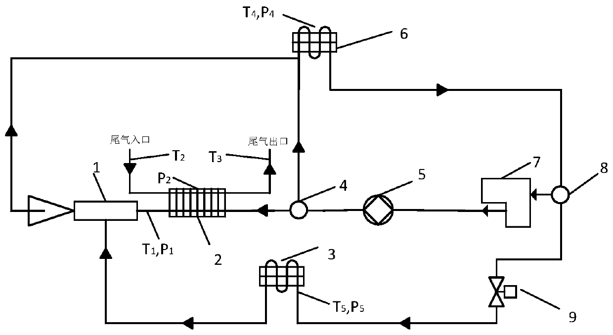
The invention provides a device and method for driving an injection type refrigerating system through automobile waste heat recovery. The device comprises an automobile tail gas heat exchanger. The automobile tail gas heat exchanger is used for further heating and pressurizing engine cooling liquid which reaches a set temperature threshold value and is subjected to primary pressurization, dividingthe engine cooling liquid into a first strand of primary flow and a second strand of primary flow and feeding the first strand of primary flow and the second strand of primary flow into an ejector. The first strand of primary flow forms a negative pressure zone in an ejector sucking room so as to inject secondary flow cooling liquid from the interior of an evaporator, the secondary flow cooling liquid is subjected to injection by the first strand of primary flow and is then sucked into a room at the ejector and subjected to heat exchange with the outside in the ejector sucking room so as to conduct refrigeration. The second strand of primary flow is used for injecting a mixed stream of the first strand of primary flow and a secondary flow, and enters an air cooler to be subjected to condensation heat exchange with the outside after being completely mixed with the mixed flow; and after shunting, cooling liquid subjected to condensation heat exchange in one path is used for cooling an engine and is recycled to the automobile tail gas heat exchanger again, and cooling liquid subjected to condensation heat exchange in another path is throttled and then enters the evaporator to form secondary flow cooling liquid.

Description

technical field [0001] The present disclosure relates to the field of recycling automobile waste heat for refrigeration, and in particular to a device and method for driving an ejection refrigeration system by recycling automobile waste heat. Background technique [0002] The statements in this section merely mention background art related to the present disclosure and do not necessarily constitute prior art. [0003] When the car is running, a lot of heat is wasted in the form of car exhaust and engine heat dissipation, and this part of heat even accounts for more than 70% of the fuel consumption of the car. And when the car turns on the air conditioner in summer, it needs to increase fuel consumption. By collecting the waste heat of the car and using it to drive the jet refrigeration system, the cooling can be realized and the fuel consumption of the car when the air conditioner is turned on in summer can be reduced. As far as the inventors know, the existing waste heat-...

Claims


Application Information

Patent Timeline
Patent Type & Authority Applications(China)
IPC IPC(8): F25B27/02F25B9/08F25B41/00F25B41/04F25B41/06F02G5/00F25B41/20F25B41/34F25B41/40
CPCF25B27/02F25B9/08F25B41/00F02G5/00F25B2341/0012F25B41/20F25B41/31Y02A30/274Y02T10/12
Inventor 张海伦王雷贾磊
Owner SHANDONG UNIV
Learn More