Embedded anterior cervical compression fusion fixing device

An anterior cervical spine and fixation device technology, applied in the direction of joint implants, joint implants, spinal implants, etc., can solve problems such as prone to complications and difficult anterior cervical surgery, and achieve improved fit The effect of improving stability, reducing bone plate notch, and increasing fit

Pending Publication Date: 2019-07-19
云南欧铂斯医疗科技有限公司
View PDF0 Cites 1 Cited by
  • Summary
  • Abstract
  • Description
  • Claims
  • Application Information

AI Technical Summary

Problems solved by technology

However, anterior cervical surgery is more difficult and prone to complications

Method used


Image

  • Embedded anterior cervical compression fusion fixing device
  • Embedded anterior cervical compression fusion fixing device
  • Embedded anterior cervical compression fusion fixing device

Examples


Embodiment 1

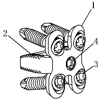
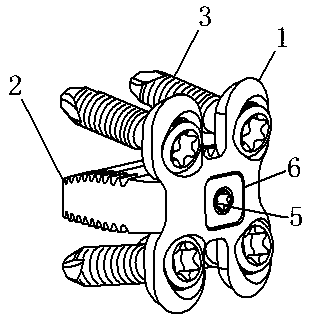
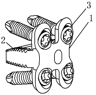
[0045] Embedded anterior cervical spine compression fusion fixation device, the fixation device includes: fixation screws 3 and a vertebral body bone plate 1; the vertebral body bone plate 1 is provided with at least one axial end at each end of the axial direction consistent with the axis of the spine. The convex angle 101, the convex angle of the vertebral body bone plate 1 is provided with a convex structure 102 that can be embedded in the vertebral body on the side facing the vertebral body bone, and the convex structure can be embedded in the bone groove 7 matched with the front edge of the vertebral body during use, In order to reduce the notch of the bone plate and increase the stability of the bone plate fixation.

[0046]A round-like screw hole 103 is arranged on the convex corner. The axial direction of the screw hole 103 and the main plane of the vertebral body bone plate 1 are multi-directional and single-angle design. The inner surface of the screw hole 103 is prov...

Embodiment 2

[0048] On the basis of Example 1, the thickness of the protruding corner 101 does not exceed 3.5 mm; the periphery of the protruding structure where the protruding corner can be embedded in the vertebral body is a protruding skirt structure 104, and the thickness of the skirt edge 104 does not exceed 3.5 mm. 1.5mm, when in use, the convex structure 102 of the convex angle is embedded in the vertebral body bone groove 7, and the convex angle skirt structure 104 covers the outer edge of the vertebral body bone groove 7 to realize low-profile fixation. The actual use of bone plate cutting The trace does not exceed 1.5mm.

Embodiment 3

[0050] On the basis of Example 1, the side of the vertebral body bone plate 1 facing the human bones is provided with a columnar intervertebral fusion body 2; The vertebral body bone plate 1 can be in the required shape such as M-shaped, H-shaped, I-shaped or triangular, and the integrated connection can use the same material body to prepare the vertebral body bone plate 1 and the vertebral body. The intervertebral fusion body 2 can be produced by 3D printing, and the production cost is lower; the vertebral body bone plate 1 and the intervertebral fusion body 2 with split screw connection or snap connection can be made of different materials and have stronger applicability.


PUM


Abstract

The invention relates to the field of orthopedic surgery medical instruments, in particular to an embedded anterior cervical compression fusion fixing device. The device comprises fixing screws and avertebral bone plate; the vertebral bone plate is provided with at least one convex angle at two axial ends which are consistent with the axial direction of the vertebral column, and the back surfaceof the convex angle of the vertebral bone plate is provided with a convex structure which can be embedded into the vertebral body; the convex angle is provided with a round-like screw hole, and the inner surface of the screw hole is provided with an internal thread; the curvature of the top end of the round-like screw hole is larger than that of the low end of the round-like screw hole; one end, opposite to the cervical vertebra skeleton, of the screw hole is provided with a screw hole inclined plane which inclines inwards; and the fixing screws fix the vertebral bone plate on the cervical vertebra skeleton through the screw holes. The device can reduce vertebral bone plate incisura, realize intervertebral compression, increase the stability of the vertebral bone plate and effectively improve the intervertebral fusion rate.

Description

technical field [0001] The invention relates to the field of orthopaedic surgical medical instruments, in particular to an embedded anterior cervical vertebra compression fusion and fixation device. Background technique [0002] In recent years, anterior cervical spine surgery has been popularized and applied in more and more hospitals, and has achieved remarkable curative effects in the treatment of cervical spine degenerative diseases, trauma, tumors, inflammation and deformity. However, anterior cervical spine surgery is difficult and prone to complications. At present, the reported common complications of anterior cervical spine surgery include spinal cord injury, nerve injury, vascular injury, respiratory tract injury, esophagus injury, cerebrospinal fluid leakage, epidural hematoma formation and implant failure. [0003] Cervical spondylosis myelopathy and cervical radiculopathy are common and frequently-occurring diseases in the middle-aged and elderly population. Wi...

Claims


Application Information

Patent Timeline
Patent Type & Authority Applications(China)
IPC IPC(8): A61F2/44A61F2/30
CPCA61F2/4455A61F2/30749A61F2002/30426A61F2002/30818A61F2002/30433
Inventor 熊鹰王帆黄子毅陆俊雄
Owner 云南欧铂斯医疗科技有限公司
Why Eureka
Try Eureka