
Photovoltaic solar energy production battery piece and welding strip bonding and welding clamp

A technology of photovoltaic solar energy and welding fixtures, which is applied in the direction of welding equipment, auxiliary welding equipment, welding/cutting auxiliary equipment, etc., and can solve the problem of incorrect placement of the welding joint between the ribbon and the battery sheet, damage to the battery sheet, and irregular welding, etc. Problems, to achieve the effect of stable clamping, damage prevention, and not easy damage

Active Publication Date: 2019-07-19
ZHEJIANG TRUMHE NEW MATERIAL CO LTD
View PDF10 Cites 0 Cited by
  • Summary
  • Abstract
  • Description
  • Claims
  • Application Information

AI Technical Summary

Problems solved by technology

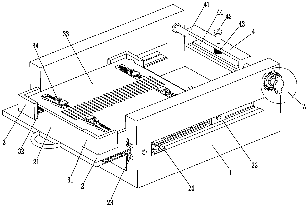
[0005] In order to solve the above problems, the present invention provides a bonding welding jig for photovoltaic solar energy production between cells and ribbons, which can solve the main problem in the manual welding process a: the operator often causes damage to the cells due to uneven control of the welding force ;b: The welding joints of the ribbon and the battery sheet are not aligned, resulting in irregular welding; affecting the use; c: During the welding process, due to the light weight of the battery sheet, the battery sheet moves during the welding of the ribbon and needs to be re-aligned Welding parts, affecting the welding efficiency and the appearance of the components, etc., can realize the function of being convenient for welding workers to weld, with stable clamping, not easy to cause damage to the battery sheet, easy to adjust the connection angle between the welding strip and the battery sheet, and ensuring the welding Advantages such as the welding quality between the ribbon and the cell

Method used


Image

  • Photovoltaic solar energy production battery piece and welding strip bonding and welding clamp
  • Photovoltaic solar energy production battery piece and welding strip bonding and welding clamp
  • Photovoltaic solar energy production battery piece and welding strip bonding and welding clamp

Examples


Embodiment Construction

[0026] In order to make the technical means, creative features, goals and effects achieved by the present invention easy to understand, the present invention will be further described below in conjunction with specific illustrations. It should be noted that, in the case of no conflict, the embodiments in the present application and the features in the embodiments can be combined with each other.

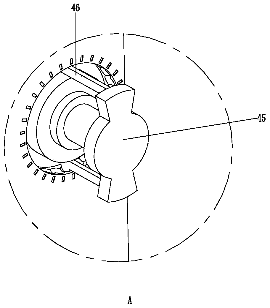
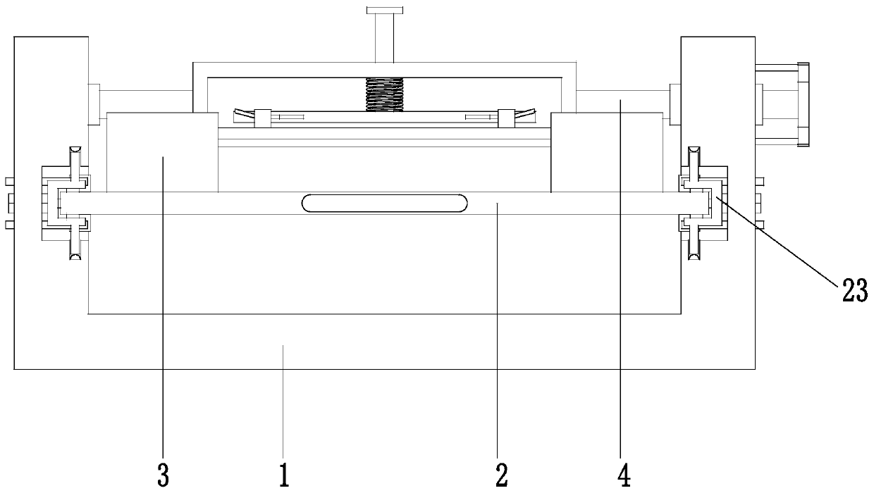
[0027] Such as Figure 1 to Figure 4 As shown, a welding jig for photovoltaic solar energy production with a battery sheet and a welding ribbon, including a U-shaped frame 1, an actuator 2, a fixing mechanism 3 and an auxiliary mechanism 4; the left end of the U-shaped frame 1 is installed through a movable fit There is an auxiliary mechanism 4; the middle part of the U-shaped frame 1 is provided with a rectangular cut hole, and a movable groove is arranged in the rectangular cut hole, and balls are evenly arranged in the described movable groove; The matching method is installed wi...


PUM


Abstract

The invention provides a photovoltaic solar energy production battery piece and welding strip bonding and welding clamp. The clamp comprises a U-shaped frame, an actuator, a fixing mechanism and an auxiliary mechanism. The clamp can solve the main problems that in the manual welding process, a, battery pieces are often damaged due to uneven control over welding intensity of operators, b, welding is irregular due to the fact that welding grooves of welding strips and the battery pieces are not aligned, and application is affected, and c, the battery pieces move in the welding process of the welding strips due to low weight of the battery pieces during welding, welded parts need to be aligned again, the welding efficiency is affected, and the appearance of components is affected. The function of facilitating welding by welding workers can be achieved and has the advantages that clamping is stable, the battery pieces are not liable to be damaged, the connection angle between the welding strips and the battery pieces is convenient to adjust, and the welding quality between the welding strips and the battery pieces is ensured.

Description

technical field [0001] The invention relates to the technical field of welding tools, in particular to a welding jig for laminating battery sheets and welding strips for photovoltaic solar energy production. Background technique [0002] In the prior art, welding is used between the battery sheet and the soldering ribbon, and the soldering ribbons commonly used are divided into two types, lead soldering ribbon and lead-free soldering ribbon; manual soldering is mainly used, but the following problems mainly exist in the manual soldering process: [0003] a: Due to the uneven control of the welding force, the operator often causes damage to the battery sheet; b: The soldering joints of the welding ribbon and the battery sheet are not aligned, resulting in uneven welding; affecting the use; c: During the welding process, due to the light weight of the battery sheet As a result, the cell moves during the welding of the ribbon, and the weldment needs to be re-aligned, which affe...

Claims


Application Information

Patent Timeline
Patent Type & Authority Applications(China)
IPC IPC(8): B23K37/04
CPCB23K37/0443
Inventor 孙益民邓琴
Owner ZHEJIANG TRUMHE NEW MATERIAL CO LTD
Learn More