Ceramic honeycomb filter, exhaust gas-purifying device, and exhaust gas-purifying method

A ceramic honeycomb and filter technology, which is applied in the field of exhaust purification, can solve problems such as the temperature rise of the exhaust gas and the damage of the inflow side plugging part, so as to prevent the increase of pressure loss, eliminate clogging, and avoid damage or melting loss. Effect

Inactive Publication Date: 2006-12-06
HITACHI METALS LTD +1
View PDF4 Cites 3 Cited by
  • Summary
  • Abstract
  • Description
  • Claims
  • Application Information

AI Technical Summary

Problems solved by technology

[0011] However, in the case of this honeycomb filter, the temperature of the exhaust gas rises rapidly near the inflow-side plugging portion every time fuel is injected, and the inflow-side plugging portion may be damaged if it is used for a long time.

Method used


Image

  • Ceramic honeycomb filter, exhaust gas-purifying device, and exhaust gas-purifying method
  • Ceramic honeycomb filter, exhaust gas-purifying device, and exhaust gas-purifying method
  • Ceramic honeycomb filter, exhaust gas-purifying device, and exhaust gas-purifying method

Examples


Embodiment 1~5

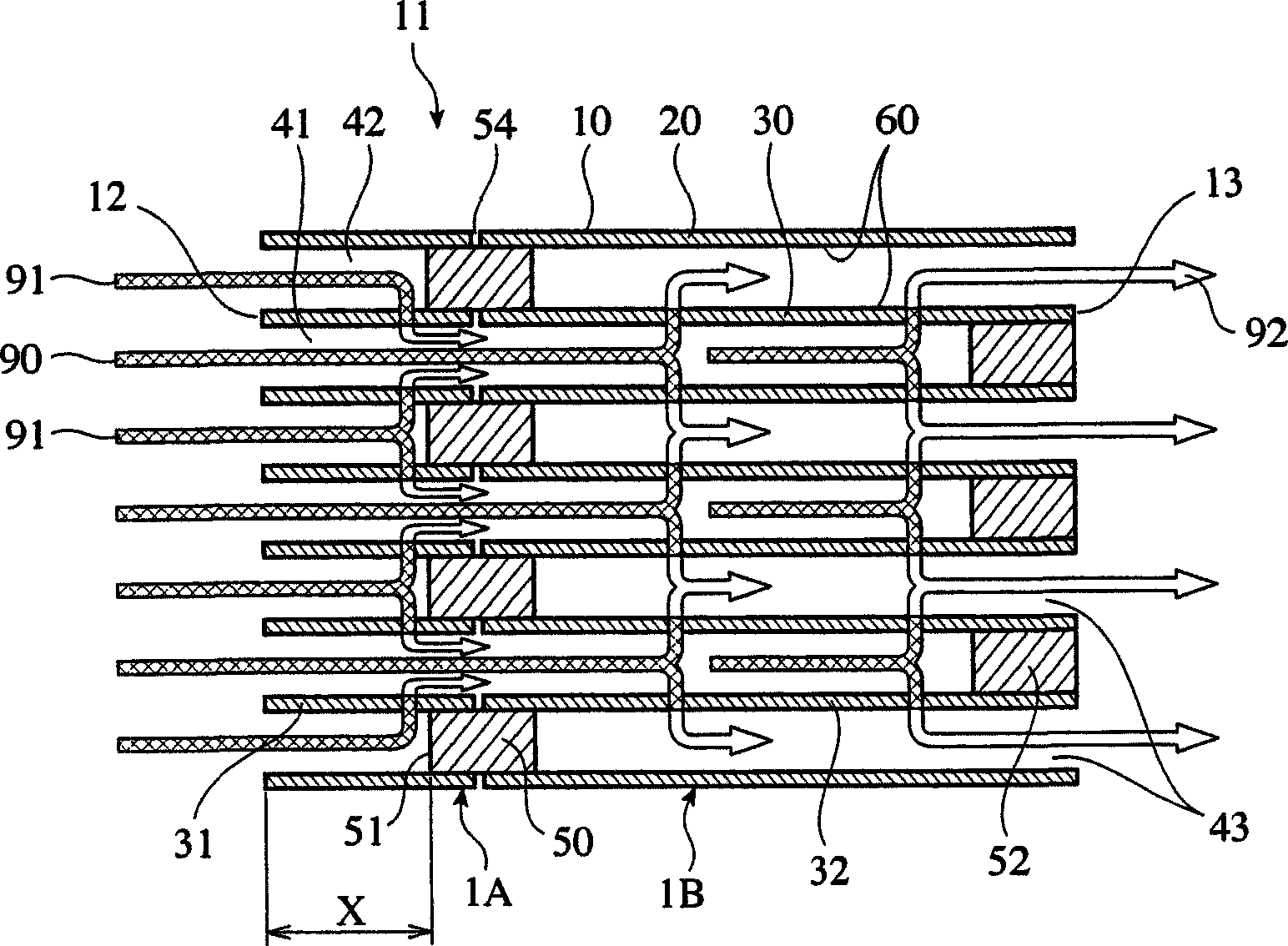
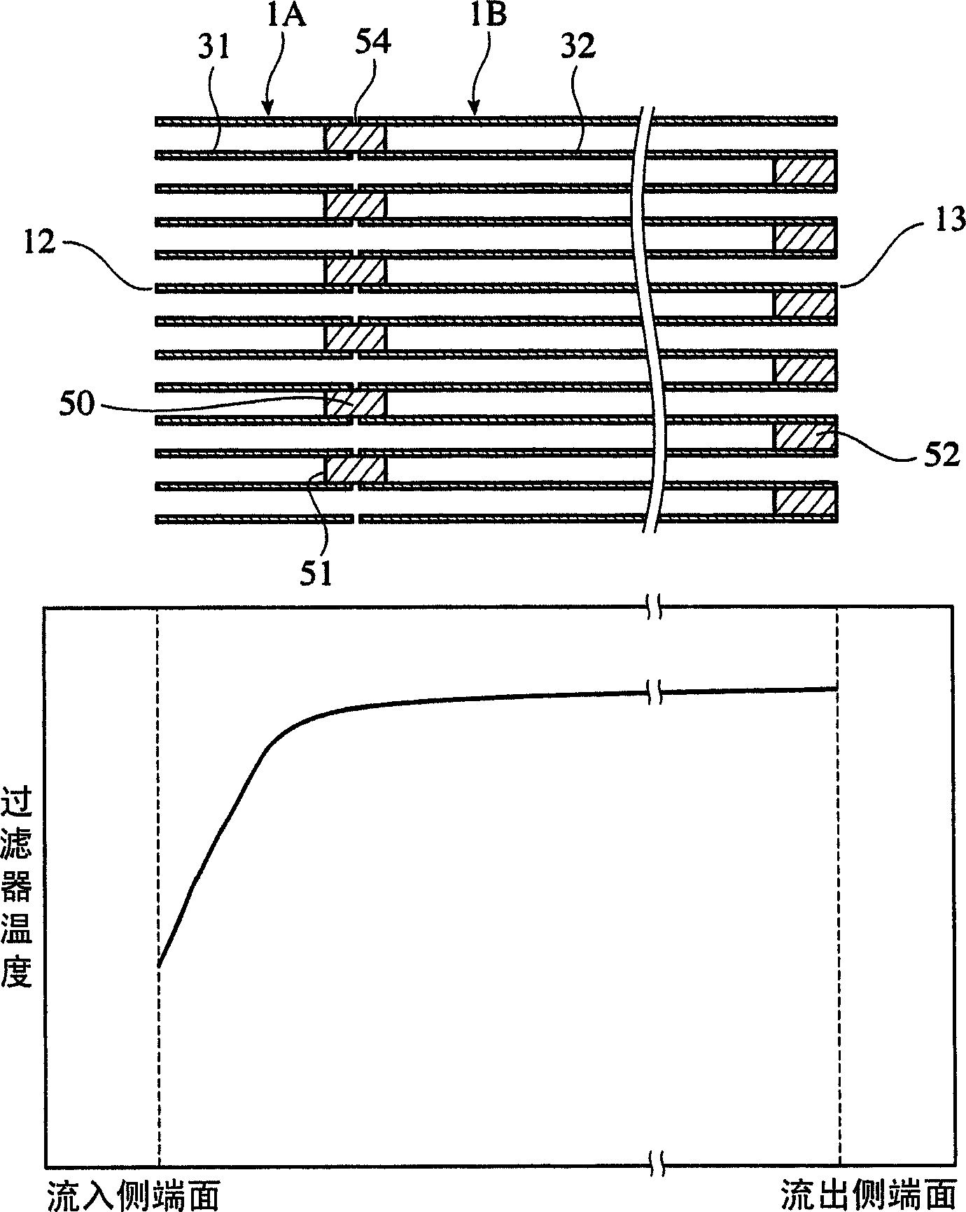
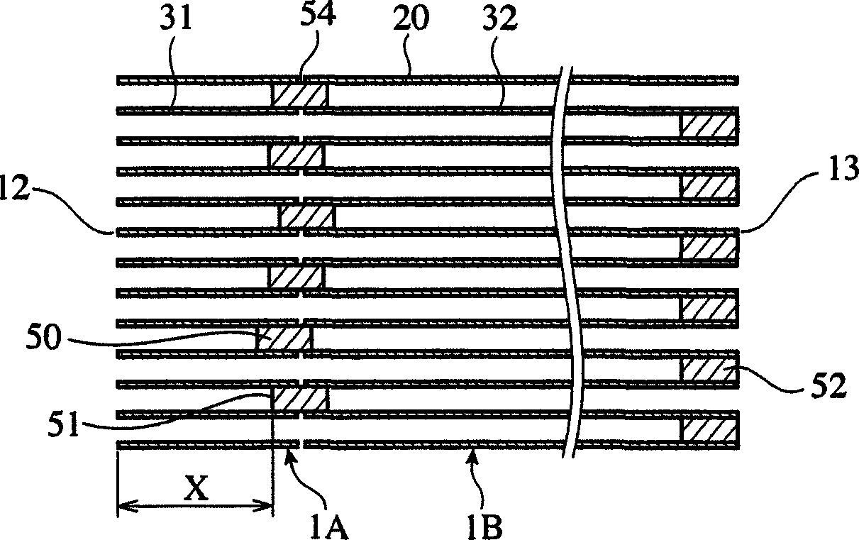
[0084] Prepare kaolin, talc, silica, aluminum hydroxide, alumina and other powders to obtain SiO 2 : 47~53%, Al 2 o 3 : 32-38%, MgO: 12-16%, and CaO, Na 2 O, K 2 O, TiO 2 , Fe 2 o 3 , PbO, P 2 o 5Inevitably mixed ingredients: 2.5% (accounting for the mass ratio of the whole) cordierite raw material powder below 2.5%, add forming aids and pore-forming agents, inject a specified amount of water, further fully mix, and prepare to be extruded into Clay with honeycomb structure. Next, extrusion molding is performed using a known extrusion molding die to manufacture a molded body having a honeycomb structure having an outer peripheral wall 20 and a flow path with a square cross section surrounded by a partition 30 on the inner peripheral side of the outer peripheral wall 20. , fired after drying, and manufactured a honeycomb structure 1A with an exhaust gas inflow side partition 31 and a honeycomb structure 1B with an exhaust gas outflow side partition 32, the exhaust gas i...

Embodiment 6

[0098] By the same method as in Example 2, a honeycomb having a separator structure with a separator pitch of 1.5 mm and a separator thickness of 0.3 mm, a separator with a porosity of 65%, a diameter of 267 mm, and a total length of 96.4 mm was fabricated. A honeycomb structure 1A, and a honeycomb structure 1B having a spacer of 1.5 mm, a thickness of 0.3 mm, a porosity of 65%, a diameter of 267 mm, and a total length of 208.3 mm. . To the end of the flow path of the honeycomb structure 1A and the honeycomb structure 1B, a raw material containing a plasticizing plugging material is inserted to form a checkered pattern, and then the honeycomb structure 1A The honeycomb structures 1A and 1B are integrated by forming a gap 54 of 0.1 mm between them and the separator of 1B.

[0099] On the other end surface 13 of the honeycomb structure 1B, a resin film is pasted, the film is perforated alternately with the inflow-side plugging parts 50, a raw material-like plugging material is ...

Embodiment 7

[0103] By the same method as in Example 2, a honeycomb having a separator structure with a separator pitch of 1.5 mm and a separator thickness of 0.3 mm, a separator with a porosity of 65%, a diameter of 267 mm, and a total length of 96.9 mm was fabricated. Honeycomb structure 1A, and a honeycomb structure 1B having a separator structure with a separator pitch of 1.5 mm and a separator thickness of 0.3 mm, a separator with a porosity of 65%, a diameter of 267 mm, and a total length of 206.9 mm . In addition, plugging portions 50 were used to integrate them, and the gap 54 was set to 1 mm, and plugging portions 52 were formed alternately with plugging portions 50 on the other end surface 13 of the honeycomb structure 1B.

[0104] On the honeycomb structure 1A and the plugging portion 50, Pt, cerium oxide, and activated alumina (catalyst B) are loaded so that the loading amount of cerium oxide and activated alumina is the same as that of catalyst A, and the loading amount of Pt ...


PUM

PropertyMeasurementUnit
porosityaaaaaaaaaa
porosityaaaaaaaaaa
porosityaaaaaaaaaa

Abstract

Provided are a ceramic honeycomb filter, an exhaust gas- purifying device constituted of a ceramic honeycomb filter and of a fuel supply device provided on the upstream of the ceramic honeycomb filter, and an exhaust gas-purifying method using a ceramic filter. A ceramic honeycomb filter where porous ceramic honeycomb structure bodies (1A, 1b) having a large number of flow paths (41, 42, 43) partitioned by partition walls (30) are joined in the flow path direction, desired flow paths are sealed, and fine holes formed in the partition walls (30) are subjected to exhaust gas passage, wherein partition walls (31) of at least one honeycomb structure (1A) and partition walls (32) of a honeycomb structure (1b) adjacent to this honeycomb structure (1A) are joined so as to have gaps (54), in the flow path direction, at a sealing section (50), and wherein catalyst is carried at the partition walls (30) and / or at least part of sealing sections (50, 52).

Description

technical field [0001] The present invention relates to a ceramic honeycomb filter suitable for use as a device for removing particulates contained in gas exhausted from a diesel engine, an exhaust purification device having the ceramic honeycomb filter, and an exhaust purification method. Background technique [0002] In recent years, in order to remove particulates mainly composed of carbon from the exhaust gas of diesel engines, ceramic honeycomb filters (hereinafter referred to as "ceramic honeycomb filters" which alternately block a plurality of flow paths of a ceramic honeycomb structure at both ends) have been used. Honeycomb filter" is referred to as "honeycomb filter"). [0003] Generally, a honeycomb filter is composed of an outer peripheral wall and a porous ceramic honeycomb structure (hereinafter referred to as "porous ceramic honeycomb structure") having a plurality of flow paths surrounded by separators on the inner peripheral side of the outer peripheral wall...

Claims


Application Information

Patent Timeline
Patent Type & Authority Applications(China)
IPC IPC(8): F01N3/02B01D39/14B01D53/92B01J35/04B01D46/00B01D46/24
CPCF01N2510/0682B01D46/2459F01N2330/30B01D2046/2496B01D46/0063B01D46/2466F01N2013/026Y02T10/20B01J35/04F01N3/0222B01D46/2455B01D46/2474B01D2046/2488B01D46/2451B01D2046/2492F01N13/0097Y02T10/12B01D46/2498B01D46/84B01D46/2482F01N3/02B01D39/14F01N3/022
Inventor 诹访部博久渡边一丰杉原启之高仓隆中込惠一
Owner HITACHI METALS LTD
Why Eureka
Try Eureka