
Novel embossing mechanism of forming box embossing machine

An embossing machine and embossing technology, applied in decorative arts, painting tools, embossed decorative parts, etc., can solve the problems of troublesome replacement of hydraulic embossing machines, different embossing depths, etc., to improve the yield and production efficiency, The effect of uniform embossing, improving indentation effect and yield rate

Pending Publication Date: 2019-07-19
ZHEJIANG CEN TAI MACHINERY
View PDF0 Cites 0 Cited by
  • Summary
  • Abstract
  • Description
  • Claims
  • Application Information

AI Technical Summary

Problems solved by technology

[0002] The traditional hydraulic embossing machine includes an upper beam, a movable beam and a lower beam. The upper beam, the movable beam and the lower beam are rigidly connected by four columns and nuts, and the oil cylinder is fixed on the upper beam. The flange and the bolts are rigidly connected into one body, and the lower cross beam is provided with a fixed workbench on which the workpiece to be pressed is placed. When working, the product is put into the fixed workbench for pressing, but the same hydraulic embossing machine is relatively different in height. The embossed workpiece has different embossing depths, and sometimes the pressed workpiece will be pressed through, and when embossing the pressed workpiece with different specifications, it is necessary to replace the fixed worktable that matches the pressed workpiece. But the traditional hydraulic embossing machine is troublesome to replace

Method used


Image

  • Novel embossing mechanism of forming box embossing machine
  • Novel embossing mechanism of forming box embossing machine
  • Novel embossing mechanism of forming box embossing machine

Examples


Embodiment Construction

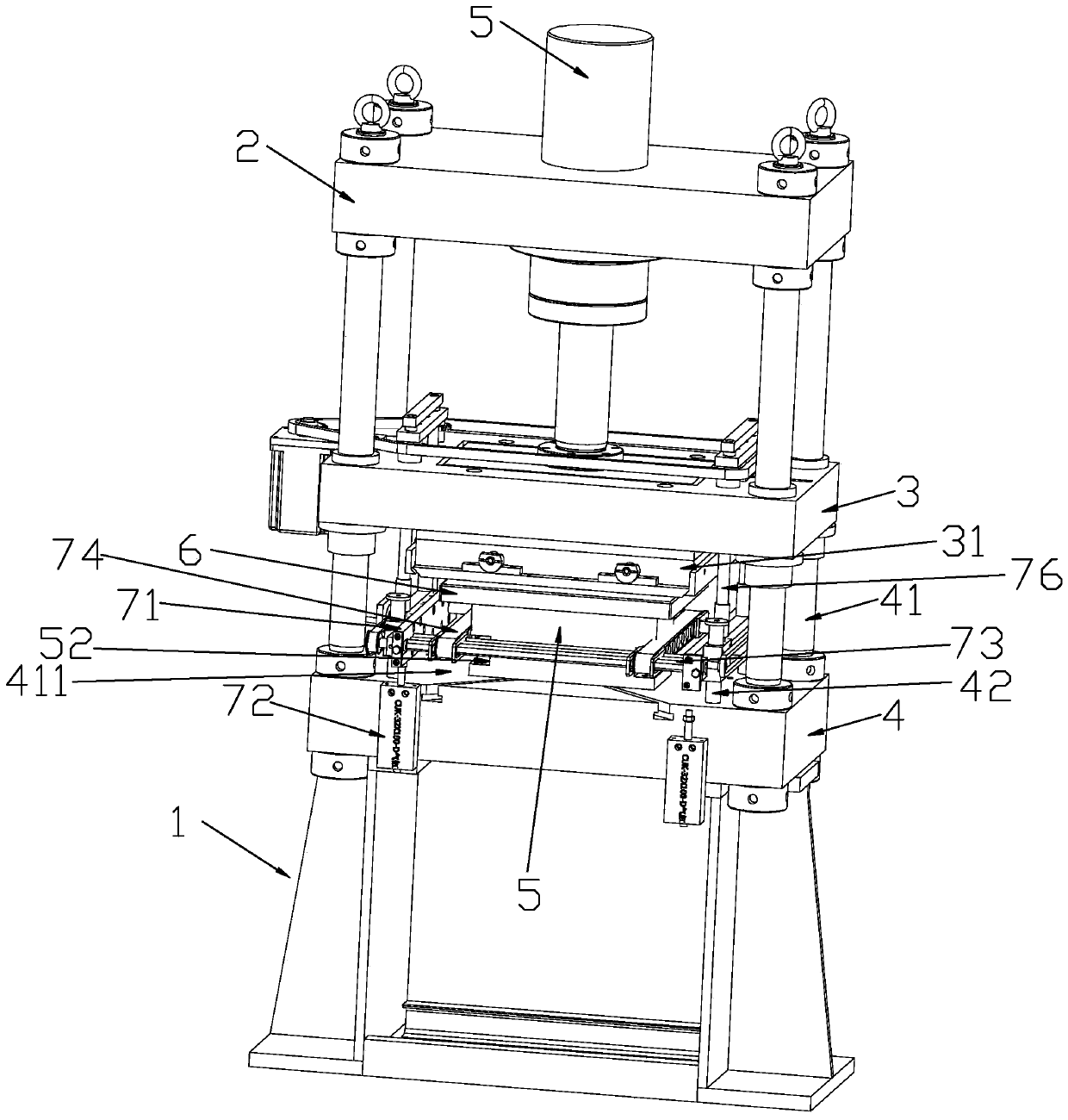
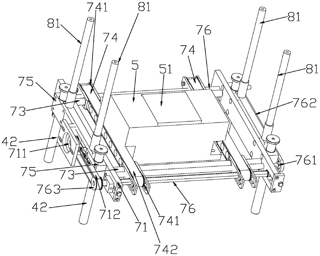
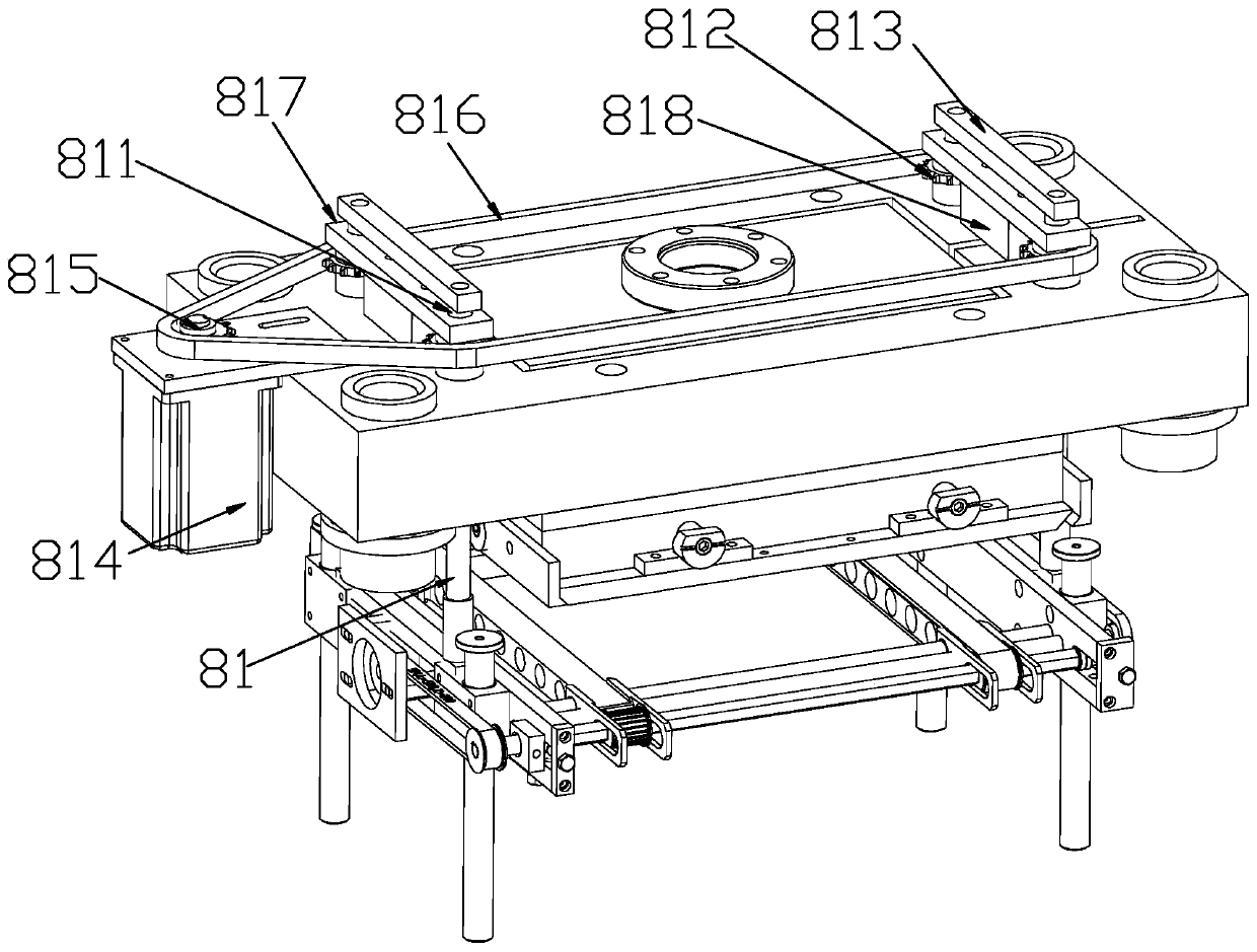
[0018] see Figure 1-Figure 3Shown: a new embossing mechanism of a forming box embossing machine, including a support frame 1, an upper beam 2, a movable beam 3 and a lower beam 4, the lower beam 4 is set at the end of the support frame 1 away from the ground, and the lower beam 4 There are four columns 41 on the top, the movable beam 3 and the upper beam 2 are sequentially installed on the columns 41, the oil cylinder 5 is fixed on the upper beam 2, the piston, the piston rod and the movable beam 3 are rigidly connected into one body by flanges and bolts. A workbench 5 is arranged between the crossbeam 3 and the lower crossbeam 4, an upper embossing die 31 is connected to the end of the movable crossbeam 3 facing the lower crossbeam 4, and a lower embossing die 31 opposite to the upper embossing die 31 is arranged in the workbench 5 51, the pressed workpiece 6 is set on the lower embossing mold 51, and there is a device between the movable beam 3 and the lower beam 4. When th...


PUM


Abstract

The invention relates to a novel embossing mechanism of a forming box embossing machine. A supporting frame, an upper beam, a movable beam and a lower beam are included. The lower beam is arranged atthe end, away from the ground, of the supporting frame. The lower beam is provided with four stand columns. An oil cylinder is fixed to the upper beam. A piston, a piston rod and the movable beam arein rigidity connection into a whole through flanges and bolts. A workbench is arranged between the movable beam and the lower beam. The end, towards the lower beam, of the movable beam is provided with an upper embossing die. A lower embossing die opposite to the upper embossing die is arranged in the workbench. A pressed workpiece is arranged on the lower embossing die. A bracket mechanism is arranged between the movable beam and the lower beam and plays a buffering role on the pressed workpiece when the oil cylinder drives the upper beam to emboss the pressed workpiece on the workbench. Thenovel embossing mechanism has the beneficial effects that the bracket mechanism is arranged so that the pressed workpiece buffering indentation can be achieved, the buffering indentation distance canbe adjusted, and the indentation effect and yield are obviously improved.

Description

technical field [0001] The invention relates to the field of forming box intelligent embossing machines, in particular to a novel embossing mechanism of the forming box embossing machine. Background technique [0002] The traditional hydraulic embossing machine includes an upper beam, a movable beam and a lower beam. The upper beam, the movable beam and the lower beam are rigidly connected by four columns and nuts, and the oil cylinder is fixed on the upper beam. The flange and the bolts are rigidly connected into one body, and the lower cross beam is provided with a fixed workbench on which the workpiece to be pressed is placed. When working, the product is put into the fixed workbench for pressing, but the same hydraulic embossing machine is relatively different in height. The embossed workpiece has different embossing depths, and sometimes the pressed workpiece will be pressed through, and when embossing the pressed workpiece with different specifications, it is necessary...

Claims


Application Information

Patent Timeline
Patent Type & Authority Applications(China)
IPC IPC(8): B44B5/00B44B5/02
CPCB44B5/0057B44B5/02B44B2700/12
Inventor 陈献诚陈献东陈智杰
Owner ZHEJIANG CEN TAI MACHINERY
Learn More