Switching type turbine machine

A turbomachinery and switchable technology, which is applied in the direction of mechanical equipment, engines, non-variable pumps, etc., can solve the problems of large eddy current loss at the edge of the blade, inability to use switchable, loud noise, etc.

Inactive Publication Date: 2019-07-19
HUNAN CHUANGHUA LOW CARBON ENVIRONMENTAL PROTECTION TECH
View PDF0 Cites 3 Cited by
  • Summary
  • Abstract
  • Description
  • Claims
  • Application Information

AI Technical Summary

Problems solved by technology

[0010] The technical problem solved by the present invention is to provide a heat flow power generation device to solve the technical problems of the prior art turbomachinery with large eddy current loss at the edge of the blade, high noise, and incapable of switchable use

Method used


Image

  • Switching type turbine machine
  • Switching type turbine machine
  • Switching type turbine machine

Examples


no. 1 example

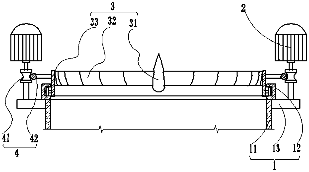
[0046] Please refer to Figure 1-3 , in a first embodiment of the invention, the switched turbomachine comprises:

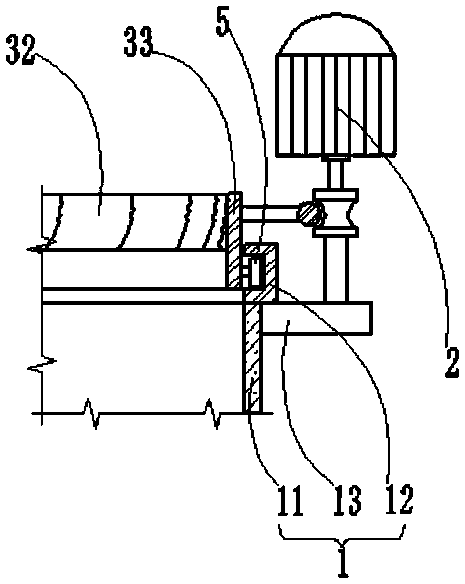
[0047] Support sleeve 1;

[0048] An electromechanical device 2, the electromechanical device 2 is arranged on the support sleeve 1;

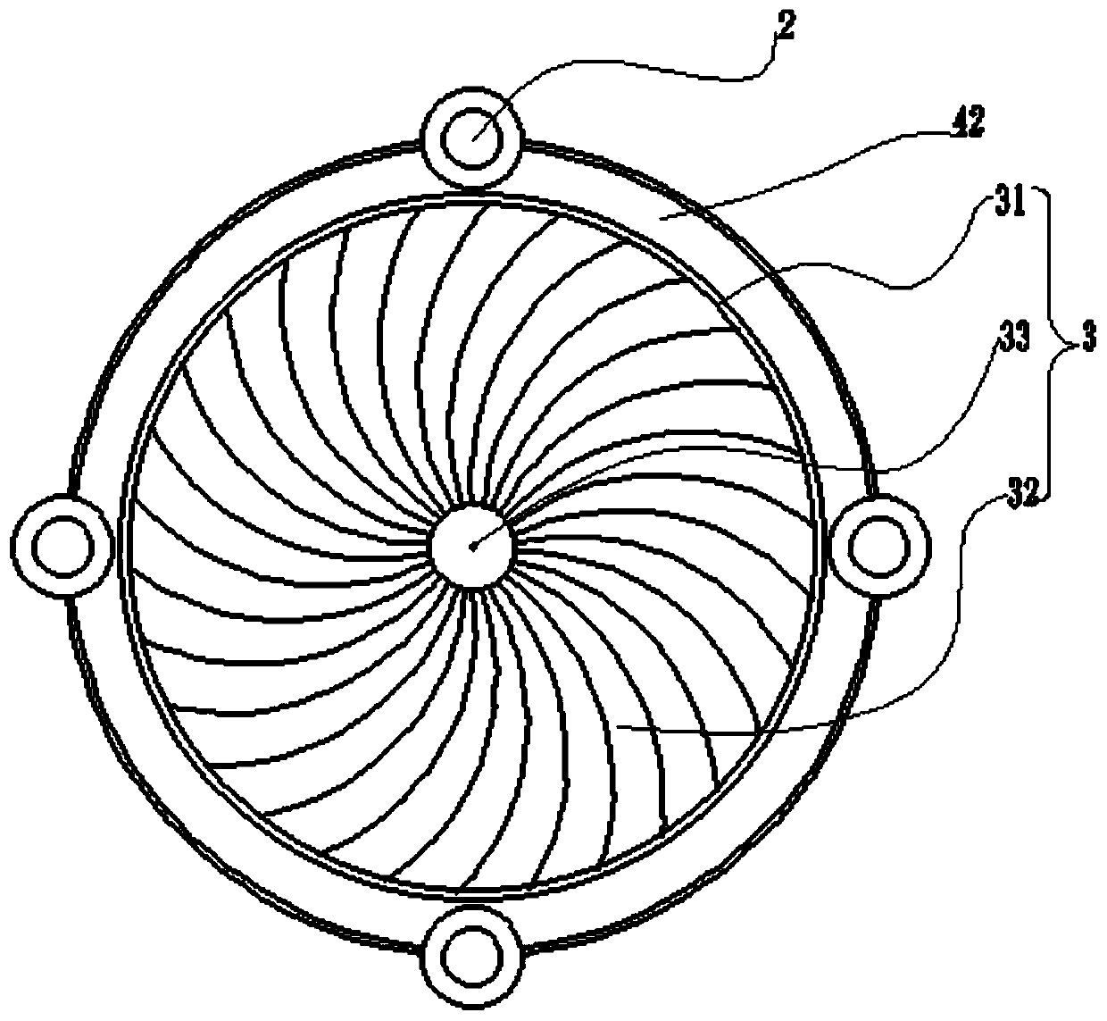
[0049] Rotating member 3, said rotating member 3 is suspended on the top of said supporting sleeve 1, said rotating member 3 includes installation shaft 31, rotating surrounding wall 33 and rotating blade 32, said rotating surrounding wall 33 surrounds said installation The shaft 31 is set, and the rotating blade 32 is connected to the installation shaft 31 and the rotating surrounding wall 33;

[0050] a transmission member 4, the transmission member 4 is used to drive and connect the rotating surrounding wall 33 and the electromechanical device 2;

[0051] Wherein, when the switchable turbomachine is switched to the wind outlet state, the electromechanical device 2 is a driving motor; the electromechanical device 2 drives the...

no. 2 example

[0071] see Figure 4 , based on the switching turbomachinery provided in the first embodiment, the difference of the switching turbomachinery provided in this embodiment is that the second transmission member 42 is arranged around the rotating wall 33, and the electromechanical device The number of 2 is one, and the switch-type turbomachine also includes a plurality of calibration wheels 6, which are arranged around the second transmission member 42, and the second transmission member 42 is transmission-connected.

[0072] In this embodiment, the calibration wheel 6 is a concentricity calibration wheel 6 .

[0073] Since the mounting shaft 31 is not provided with bearings, the concave chute structure 12 and the calibration wheel 6 can limit the fluctuation of the rotating wall 33 and the rotating blade 32 in a small space.

no. 3 example

[0075] see Figure 5 , based on the switchable turbomachinery provided in the first embodiment, the difference of the switchable turbomachinery provided in this embodiment is that the rotating member 3 also includes multiple sets of auxiliary blades 34, and multiple sets of auxiliary blades 34 are sequentially spaced It is provided on the installation shaft 31 .

[0076] In this implementation, the auxiliary blades 34 may be turbine blades; they are used to increase the wind receiving area of ​​the rotating member 3 . The auxiliary blade 34 may be connected with the rotating surrounding wall 33 ; the auxiliary blade 34 may not be connected with the rotating surrounding wall 33 .

[0077] The top of the mounting shaft 31 can be designed to be streamlined.

[0078] Switchable turbomachines can be used as wind power plants for large cooling installations or as small ventilation fans.

[0079] Switching turbomachines can be used as wind power plants and thermal gas power plants...


PUM


Abstract

The invention provides a switching type turbine machine. The switching type turbine machine comprises a supporting sleeve, electromechanical devices, a rotating part and transmission parts, wherein the electromechanical devices are arranged on the supporting sleeve, the rotating part is suspended at the top end of the supporting sleeve, the rotating part comprises a mounting shaft, a rotating surrounding wall and rotating blades, the rotating surrounding wall is arranged around the mounting shaft, the rotating blades are connected with the mounting shaft and the rotating surrounding wall, thetransmission parts are used for being in transmission connection with the rotating surrounding wall and the electromechanical devices, when the switching type turbine machine is switched to an air outlet state, the electromechanical devices are driving motors, the electromechanical devices drive the rotating surrounding wall to rotate through the transmission parts so as to realize the effect thatthe rotating blades accelerate flowing of a fluid, when the switching type turbine machine is switched to a power generating state, the electromechanical devices are generators, and the flowing fluiddrives the rotating blades to rotate so as to realize the effect that the rotating surrounding wall drives the electromechanical devices to generate electricity through the transmission parts. The switching type turbine machine can be used as power generation equipment and wind power equipment correspondingly, and is low in energy consumption, strong in energy-saving performance and low in noise.

Description

technical field [0001] The invention relates to the technical field of turbomachinery, in particular to a switchable turbomachinery. Background technique [0002] Axial flow fans are usually used for forced heat dissipation in cooling and heat dissipation equipment. Of course, centrifugal fans and cross-flow fans are also used. The characteristic of axial flow fans is that the fluid flows along the axial direction of the blades. Such as electric fans and exhaust fans are axial fans. The centrifugal fan is to suck the fluid from the axial direction of the fan and then use the centrifugal force to suck the fluid from the axial direction of the fan and then use the centrifugal force to throw the fluid out from the circumferential direction, such as blower and range hood. Axial flow fans can be designed to have a large flow rate but a small pressure head; while centrifugal fans have a large pressure head but a relatively small flow rate. The airflow of axial fans is perpendicu...

Claims


Application Information

Patent Timeline
Patent Type & Authority Applications(China)
IPC IPC(8): F04D25/08F04D29/66F01D15/10F03D9/25
CPCF01D15/10F03D9/25F04D25/08F04D29/663Y02E10/72
Inventor 刘赟武止戈
Owner HUNAN CHUANGHUA LOW CARBON ENVIRONMENTAL PROTECTION TECH
Why Eureka
Try Eureka