
Capacity detection device for air flow velocities and detection method thereof

A technology of capacity detection and air flow rate, used in measuring devices, fluid velocity measurement, liquid/fluid solid measurement, etc., can solve problems such as inability to detect, and achieve the effect of improving accuracy, product quality, and production quality

Pending Publication Date: 2019-07-19
QUZHOU COLLEGE OF TECH
View PDF0 Cites 4 Cited by
  • Summary
  • Abstract
  • Description
  • Claims
  • Application Information

AI Technical Summary

Problems solved by technology

Therefore, air compressor testing equipment is necessary. After market research, it is found that the existing air compressor testing equipment cannot detect the air flow rate per unit time and unit volume of the air inlet of the air compressor. The flow detection of the tuyere can intuitively reflect the working efficiency of the air compressor and the quality of air compression. It is known that the air temperature, the pressure of the air to be tested, and the air quality will all affect the working efficiency of the air compressor. Therefore, it is necessary to develop a model that can simulate the air temperature. , air pressure, air quality, conventional air flow rate and other environmental variables of the air flow rate capacity detection device, and provide a description of the detection method

Method used


Image

  • Capacity detection device for air flow velocities and detection method thereof
  • Capacity detection device for air flow velocities and detection method thereof
  • Capacity detection device for air flow velocities and detection method thereof

Examples


Embodiment 1

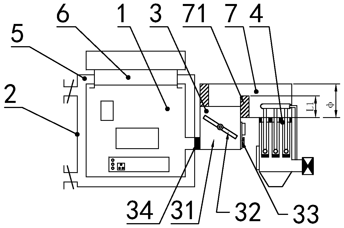
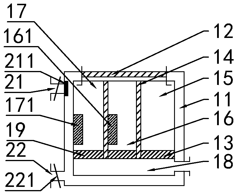
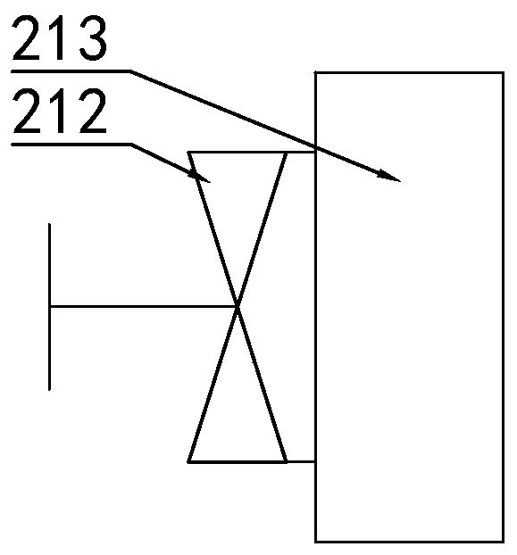
[0036] Such as Figure 1-Figure 5 As shown, the present invention discloses a capacity detection device for air flow velocity. In a specific embodiment of the present invention, it includes a flow velocity detection box 1, an air leakage detection box 2, a flow limiting device 3 and a large particle filter for filtering air. The filter device 4; the flow rate detection box 1 is arranged in the inner cavity of the air leakage detection box 2 and an air storage chamber 5 is formed between the two, the air inlet of the flow rate detection box 1 communicates with the air outlet of the flow limiting device 3, and the flow rate The air outlet of the detection box 1 passes through the side wall of the air leakage detection box 2 and extends outward to form a detection port 6 ;

[0037] In a specific embodiment of the present invention, the flow rate detection box 1 includes a box body 11 and a flow rate flowmeter 12; the flow rate flowmeter 12 is installed on the air outlet of the bo...

Embodiment 2

[0053] In addition, the present invention also discloses a capacity detection method of air flow rate, comprising the following steps:


PUM


Abstract

The invention relates to the technical field of air flow velocity detection, in particular to a capacity detection device for air flow velocities and a detection method thereof. The capacity detectiondevice for air flow velocities is characterized by comprising a flow velocity detection box, an air leakage detection box, a flow limiting device and a filter device for filtering large particles inthe air, wherein the flow velocity detection box is arranged in the inner cavity of the air leakage detection box and an air storage cavity is formed between the flow velocity detection box and the air leakage detection box; an air inlet of the flow velocity detection box is communicated with an air outlet of the flow limiting device; an air outlet of the flow velocity detection box penetrates through the side wall of the air leakage detection box and extends outwards to form a detection port; and an air inlet of the flow limiting device is communicated with the filter device through an obstruction pipeline. The capacity detection device is strong in innovativeness and practicability, and is capable of effectively detecting the air velocities at air inlets of air compressors so as to improve the production quality of the air compressors.

Description

technical field [0001] The invention relates to the technical field of air flow velocity detection, in particular to an air flow velocity capacity detection device and a detection method thereof. Background technique [0002] Air compressor products are the basic industry of the national economy. It is closely related to national defense, petroleum, chemical industry, medicine, food, urban construction, transportation, general industry and mining industry. It is an indispensable main driving force for most other industries. One of the devices. Therefore, air compressor testing equipment is necessary. After market research, it is found that the existing air compressor testing equipment cannot detect the air flow rate per unit time and unit volume of the air inlet of the air compressor. The flow detection of the tuyere can intuitively reflect the working efficiency of the air compressor and the quality of air compression. It is known that the air temperature, the pressure of ...

Claims


Application Information

Patent Timeline
Patent Type & Authority Applications(China)
IPC IPC(8): G01P5/00G01F1/00F04B51/00
CPCG01P5/00G01F1/00F04B51/00
Inventor 姜文雍毛云雁黄增阳毛方
Owner QUZHOU COLLEGE OF TECH
Learn More