Wavelength conversion device, preparation method thereof, light source device and projection equipment

A technology of wavelength conversion device and light source device, which is applied in the field of projection display, can solve problems such as yellow apertures and different proportions, and achieve the effects of reducing optical path difference, facilitating molding, and improving light extraction efficiency

Active Publication Date: 2019-07-19
APPOTRONICS CORP LTD
View PDF12 Cites 2 Cited by
  • Summary
  • Abstract
  • Description
  • Claims
  • Application Information

AI Technical Summary

Problems solved by technology

[0002] In projection equipment, the light source generally uses a blue laser chip or a blue LED chip as an excitation light source to excite the wavelength conversion device to obtain the desired light. For example, a part of the blue light can be converted into yellow light through the wavelength conversion device, and mixed with the remaining blue light to obtain white light. When the blue light passes through the existing wavelength conversion device, the optical path of the blue excitation light passing through the edge region of the wavelength conversion material is longer than the optical path of the blue excitation light passing through the central region of the wavelength conversion material, and the blue light passing through the edge of the wavelength conversion material is relatively short of the wavelength For the blue light in the central area of ​​the conversion material, the ratio of being absorbed and converted is more, so the proportion of blue light in the central area and edge area of ​​the exit spot is different, resulting in an obvious yellow halo phenomenon at the edge of the exit spot, so it is necessary to carry out the wavelength conversion device. Improve

Method used


Image

  • Wavelength conversion device, preparation method thereof, light source device and projection equipment
  • Wavelength conversion device, preparation method thereof, light source device and projection equipment
  • Wavelength conversion device, preparation method thereof, light source device and projection equipment

Examples


no. 1 example

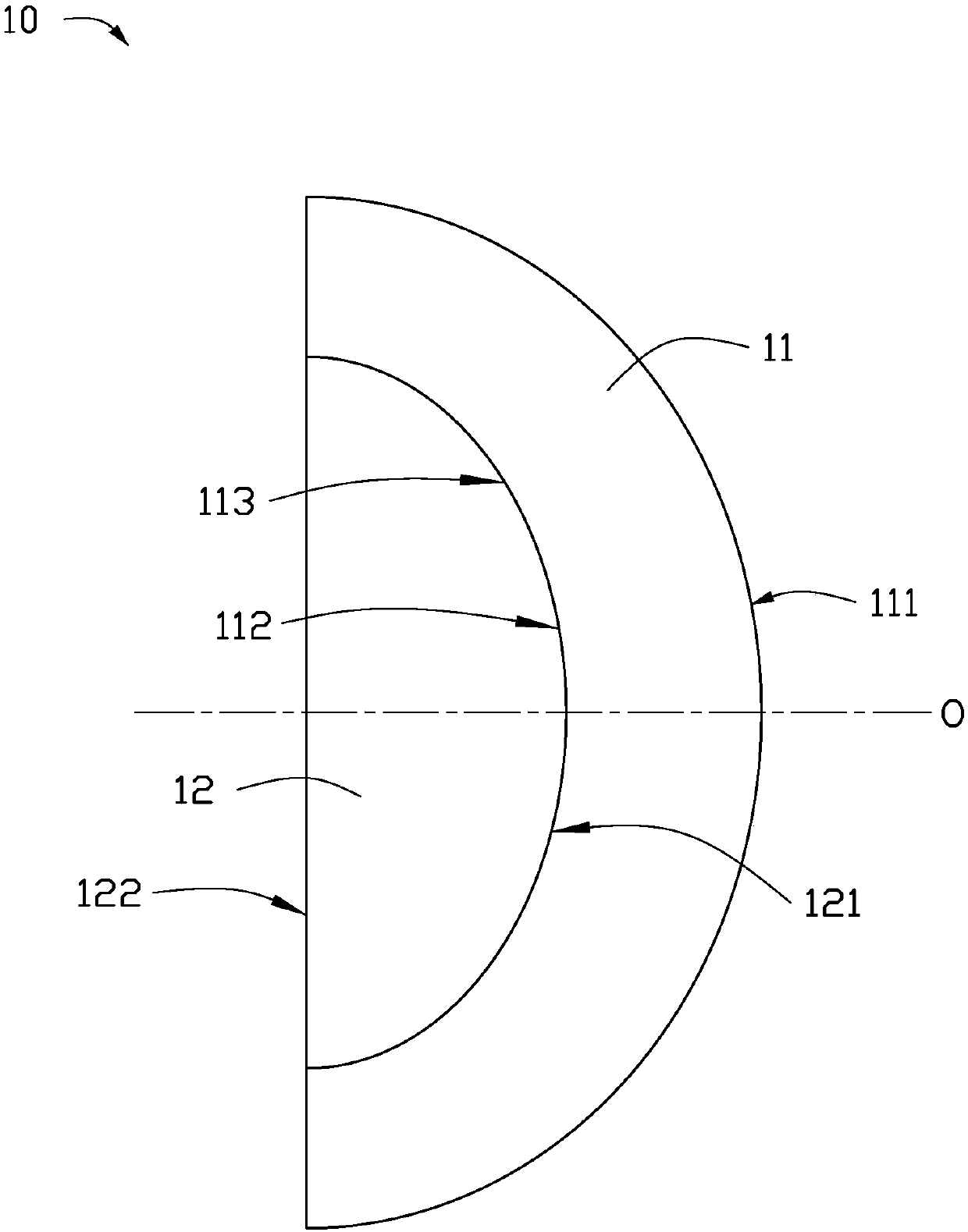
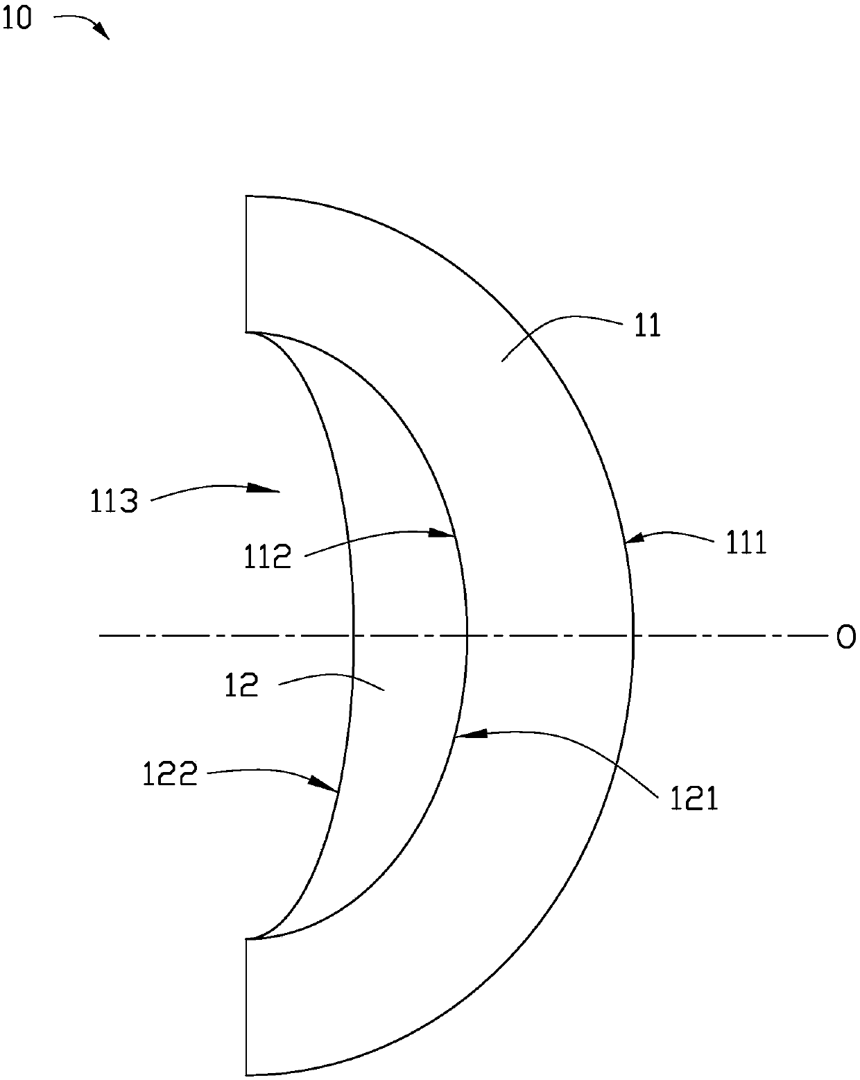
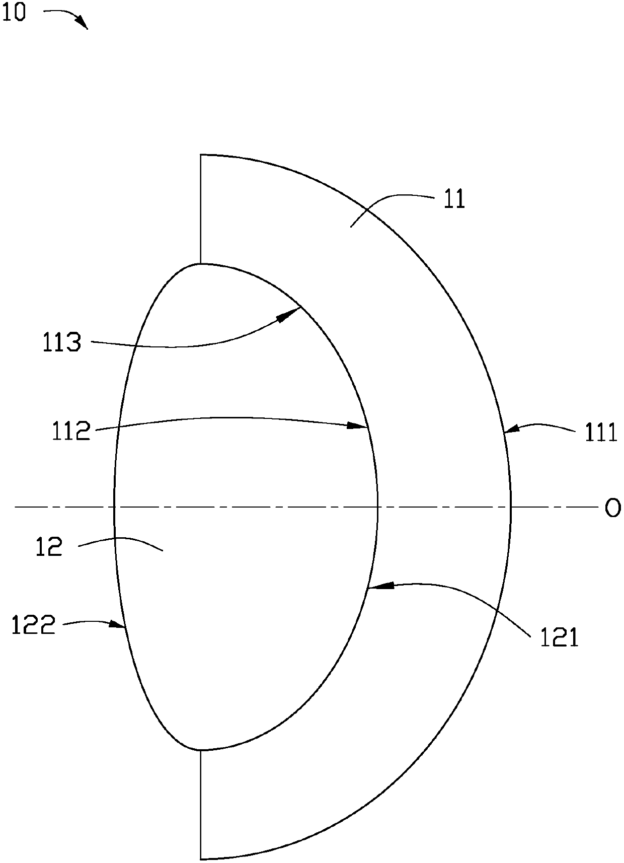
[0046] see Figure 1-3 , Figure 1-3 They are schematic structural diagrams of wavelength conversion devices 10 with different structures according to the first embodiment of the present invention. The wavelength conversion device 10 includes a meniscus lens unit 11 and a wavelength conversion unit 12 , and the meniscus lens unit 11 can serve as a support for the wavelength conversion unit 12 , functioning as a mold and a support.

[0047] The meniscus lens unit 11 includes a convex surface 111 and a concave surface 112 on the opposite side of the convex surface 111, the curvature radii of the convex surface 111 and the concave surface 112 may be the same or different, for example, the convex surface 111 And the concave surface 112 can be a spherical surface with the same or different radii, the concave surface 112 is formed with a groove 113, and one side of the wavelength conversion unit 12 is bonded to the groove 113, so that the wavelength conversion There is no air gap ...

no. 2 example

[0056] see Figure 5-7 , Figure 5-7 They are schematic structural diagrams of wavelength conversion devices 20 with different structures according to the second embodiment of the present invention. The main difference between this embodiment and the first embodiment is that this embodiment also includes a reflective layer 13, and the wavelength conversion device 20 provided in this embodiment is a reflective structure. It should be understood that each specific embodiment in the first embodiment The implementation manners can be correspondingly applied to this embodiment.

[0057] Such as Figure 5-7 As shown, a reflective layer 13 is provided on the second surface 122 of the wavelength conversion unit 12. The reflective layer 13 can cover the surface of the concave-convex lens unit 11 on the same side as the second surface 122. The reflective layer 13 can use Silicone or glass encapsulated Al 2 o 3 、TiO 2 Other white granular material. The laser light source is incide...

no. 3 example

[0061] Such as Figure 9 as shown, Figure 9 A flowchart of a method for preparing a wavelength conversion device provided by an embodiment of the present invention. The preparation of the wavelength conversion device provided by this embodiment may include the following steps:

[0062] S11: providing a meniscus lens unit.

[0063] Wherein, the meniscus lens unit 11 is used as a support body, the meniscus lens unit 11 may include a convex surface 111 and a concave surface 112 on the opposite side of the convex surface 111, the curvature of the convex surface 111 and the concave surface 112 The radii can be the same or different. The concave surface 112 is formed with a groove 113, and the groove 113 serves as a mold cavity.

[0064] The concave-convex lens unit 11 can be made of high thermal conductivity material, the thermal conductivity is preferably greater than 5W / m·K, more preferably greater than or equal to 10W / m·K, which can improve the thermal conductivity of the pre...


PUM


Abstract

The invention provides a wavelength conversion device, and the wavelength conversion device comprises a concave-convex lens unit and a wavelength conversion unit. The wavelength conversion unit is accommodated in a groove of the concave-convex lens unit, wherein one surface of the wavelength conversion unit is attached to the groove, and the thickness of the wavelength conversion unit is graduallyreduced from the central area to the peripheral edge. The invention further provides a light source device, projection equipment and a preparation method of the wavelength conversion device. According to the invention, the non-uniform light color phenomenon of emergent light spots can be effectively improved.

Description

technical field [0001] The invention relates to the technical field of projection display, in particular to a wavelength conversion device, a preparation method thereof, a light source device, and projection equipment. Background technique [0002] In projection equipment, the light source generally uses a blue laser chip or a blue LED chip as an excitation light source to excite the wavelength conversion device to obtain the desired light. For example, a part of the blue light can be converted into yellow light through the wavelength conversion device, and mixed with the remaining blue light to obtain white light. When the blue light passes through the existing wavelength conversion device, the optical path of the blue excitation light passing through the edge region of the wavelength conversion material is longer than the optical path of the blue excitation light passing through the central region of the wavelength conversion material, and the blue light passing through the...

Claims


Application Information

Patent Timeline
Patent Type & Authority Applications(China)
IPC IPC(8): G03B21/20
CPCG03B21/204G03B21/208F21V9/40G03B21/20
Inventor 徐梦梦余新胡飞李屹
Owner APPOTRONICS CORP LTD
Why Eureka
Try Eureka