Electrical switch and conductive connecting structure thereof

A conductive connection structure and electrical switch technology, applied in the direction of conductive connection, electrical component connection, connection, etc., can solve problems such as difficult to clean and difficult to find metal debris, and achieve the effects of ensuring insulation performance, easy cleaning, and good conductivity

Inactive Publication Date: 2019-07-19
HENAN PINGGAO ELECTRIC +2
View PDF1 Cites 10 Cited by
  • Summary
  • Abstract
  • Description
  • Claims
  • Application Information

AI Technical Summary

Problems solved by technology

[0005] The purpose of the present invention is to provide a conductive connection structure for an electric switch, which is used to solve the problem of metal debris that is easy to appear when the shielding cover is press-fitted and fixed on the metal insert of the pot insulator in the prior art, Difficult to clean the technical problem; Correspondingly, the present invention also provides an electrical switch using the above-mentioned conductive connection structure, which is used to solve the problem of using the contact base to press-fit and fix the shielding cover on the metal insert of the pot insulator in the prior art. It is prone to technical problems that metal debris is difficult to find and clean up

Method used


Image

  • Electrical switch and conductive connecting structure thereof
  • Electrical switch and conductive connecting structure thereof
  • Electrical switch and conductive connecting structure thereof

Examples


Embodiment 1

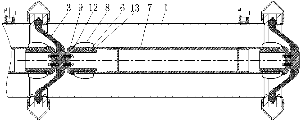
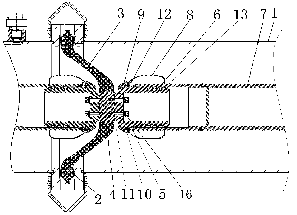
[0049] Such as figure 1 with figure 2 As shown, the conductive connection structure for an electrical switch includes two insulated cylinders 1, the opposite ends of the two cylinders 1 are fixedly assembled together, and a basin insulator 3 is sandwiched between the opposite ends of the two cylinders. 3 and the end faces of the opposite ends of the two cylinders are provided with a sealing ring 2 to realize the sealing assembly between the basin-type insulator 3 and the corresponding cylinders. Generally, an annular groove is provided on the corresponding surface of the basin insulator 3, and the sealing ring 2 can be fixed in the corresponding annular groove.

[0050] A conductive element 4 is embedded in the middle of the basin bottom of the basin insulator 3. In this embodiment, the two ends of the conductive element 4 corresponding to the two cylinders 1 are respectively fixedly provided with electrical connection contact seats 5, and the two electrical connection contacts ...

Embodiment 2

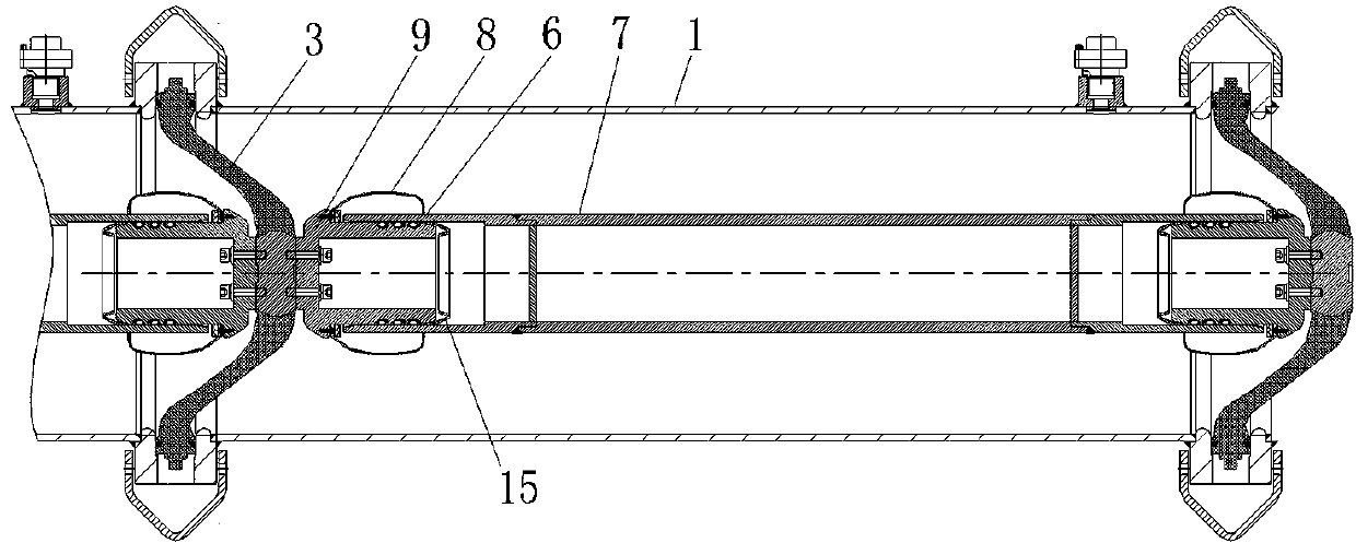
[0065] Its structure is like image 3 with Figure 4 As shown, and basically the same as the conductive connection structure in Embodiment 1, the difference is mainly: In Embodiment 1, the outer peripheral surface of the electrical connection contact seat 5 is provided with a guide ring 13 that guides the conductive tube 7, and In the second embodiment, no guide ring is provided on the outer peripheral surface of the electrical connection contact base 14, and the front end surface of the electrical connection contact base 14 is provided with a guiding plastic piece 15 that is sleeved on the outer chamfer of the front end surface. Under the action, the guiding assembly of the conductive tube 7 and the electrical connection contact base 14 can be realized.

Embodiment 3

[0067] The difference from embodiment 1 is that: in embodiment 1, the annular boss is arranged at the rear of the electrical connection contact base 5. The front side of the annular boss forms the shielding cover mounting surface, and the circumferential side wall of the annular boss and its rear The side arc transition connection, and in embodiment 3, the annular boss is arranged in the middle of the electrical connection contact seat, the front side of the annular boss forms the shielding cover mounting surface, and the circumferential side walls of the annular boss extend directly in the front and rear directions To the back end of the electrical connection contact seat, that is, the back end of the ring boss is the back end of the electrical connection contact seat. The back end of the ring boss is directly in contact with the front end of the conductive element, and the back end of the ring boss There is no cleaning interval with the basin insulator, which can reduce the cl...


PUM


Abstract

The invention relates to an electrical switch and a conductive connecting structure thereof. The electrical switch comprises the conductive connecting structure, wherein the conductive connecting structure comprises an insulating cylinder body; a basin-type insulator is arranged at the end part of the cylinder body; a conductive part is arranged on the basin-type insulator; an electric connectingcontact seat is conductively and fixedly connected to the conductive part; a conductive tube used for being matched with the front portion of the electric connecting seat in a conductive inserting-connecting mode is further arranged in the cylinder body; the electric connecting contact seat is provided with a forward shielding cover mounting surface; a shielding cover is arranged on the shieldingcover mounting surface; and the shielding cover extends forwards to at least cover the outer side of a partial inserting-connecting overlapped section of the electric connecting contact seat and the conductive tube. The shielding cover mounting surface on the electric connecting contact seat is arranged forwards, so that the shielding cover can be conveniently mounted, metal chippings generated inthe installation process of the shielding cover are not easy to hide between the conductive part and the electric connecting contact seat, the metal chippings can be found and cleaned conveniently, and the insulation performance of the conductive connecting structure and the whole electrical switch can be improved.

Description

Technical field [0001] The invention relates to an electrical switch and its conductive connection structure. Background technique [0002] At present, in gas-insulated metal-enclosed switchgear, the electrical connection method used to fix the conduit is mostly using a contact base with a spring contact finger or strap contact finger, or installing a spring contact finger or watch on the conductive tube. With fingers. [0003] For example, a conductive connection device for electrical switchgear is disclosed in the invention patent application document with the application publication number CN102709831A. In this device, the shielding cover is press-fitted on the insulating basin through a contact seat and a connection insert fixed on the insulating basin. , And contact with the conductive tube through the spring contact finger on the contact seat to realize the conductive connection between the contact seat and the conductive tube. [0004] In the process of pressing the shieldin...

Claims


Application Information

Patent Timeline
Patent Type & Authority Applications(China)
IPC IPC(8): H02B13/035H01R11/09H01R11/01H01R4/60H01R13/648
CPCH01R4/60H01R11/01H01R11/09H01R13/648H02B13/0358
Inventor 杨涛丁小洁安影黄刚毕海波康留涛李建彬李贵胜
Owner HENAN PINGGAO ELECTRIC
Why Eureka
Try Eureka