Casting nozzle

A nozzle and casting machine technology, applied in the field of casting nozzles, can solve the problems of casting material quality, molten metal cannot be uniformly input, etc., and achieve the effect of cheap manufacturing technology

Active Publication Date: 2019-07-19
SMS GRP GMBH
View PDF16 Cites 0 Cited by
  • Summary
  • Abstract
  • Description
  • Claims
  • Application Information

AI Technical Summary

Problems solved by technology

Therefore, it has the disadvantage that a plurality of such nozzles have to be switched on or operated side by side when a moving casting mold with a large width is provided.
This can lead to inhomogeneous feeding of the molten metal into the moving mold in the region where the casting nozzles adjoin each other laterally, which can cause quality problems in the resulting cast material

Method used


Image

  • Casting nozzle
  • Casting nozzle
  • Casting nozzle

Examples


Embodiment Construction

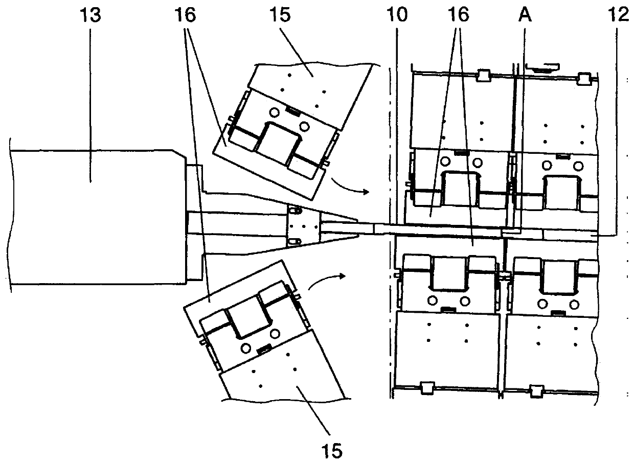
[0025] Refer below Figures 1 to 9 A preferred embodiment of a casting nozzle 10 according to the invention is described for injecting molten metal 11 , in particular non-ferrous metals such as aluminum or aluminum alloys, into a moving mold 12 of a crawler casting machine 14 . In the figures, identical features are provided with the same reference numerals. It should be pointed out here in particular that the drawings are only shown simplified and in particular not to scale.

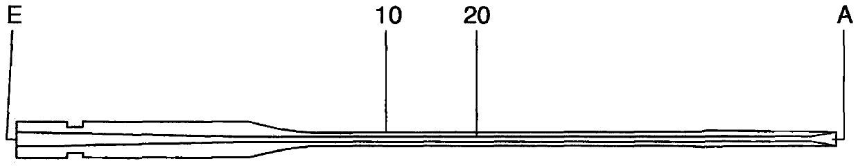
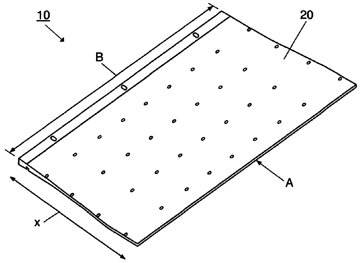
[0026] figure 1 A side view of a casting nozzle 10 according to the invention is shown, having a housing 20 with an inlet side E and an outlet side A. FIG. Housing 20 is at its height (at figure 1 in the vertical direction) is constructed in two parts and here comprises at least one upper casing 24 and at least one lower casing 26, which are separated from each other by spacers 28 (see for example Figure 6 ). Between these webs 28 the individual flow channels extend from the inlet side E to the ou...


PUM

PropertyMeasurementUnit
widthaaaaaaaaaa
thicknessaaaaaaaaaa

Abstract

The invention relates to a casting nozzle (10) for feeding molten metal into a moving casting mould of a caterpillar casting machine, comprising an elongate housing body (20) having a slot-like outletside (A), wherein a plurality of flow passages are formed in the housing body (20) along its longitudinal direction (x) and over its width direction (B), through which passages molten metal can be channelled in the direction of the outlet side (A) and can be fed from there into the moving casting mould, wherein the housing body (20) is of at least two-part design in the direction of its height and has at least one upper shell and at least one lower shell, wherein the upper shell and the lower shell are spaced apart from one another by separating webs and the individual flow passages extend between the separating webs.

Description

technical field [0001] The invention relates to a casting nozzle for injecting molten metal into a moving mold of a crawler casting machine according to the preamble of claim 1 . Background technique [0002] According to the prior art, horizontal ingot casting machines are used in particular for the production of aluminum alloys, which are operated in the manner of revolving crawler casting machines. Such casting machines are known, for example, from document EP 1 704 005 B1 or from document WO 95 / 27145. In this case, the cooling elements of the casting machine form the walls of the moving mold on the straight regions or branches of the opposing casting tracks. The cast tracks each consist of a plurality of cooling blocks connected to one another without interruption, which are conveyed along the orbiting track of the track. For this purpose, the cooling blocks are mounted on support elements which are mounted on chains and are thus articulated to each other like chain el...

Claims


Application Information

Patent Timeline
Patent Type & Authority Applications(China)
IPC IPC(8): B22D11/06
CPCB22D11/0608B22D11/0642B22D11/0688B22D11/0657
Inventor S·伯金G·菲克
Owner SMS GRP GMBH
Why Eureka
Try Eureka